Apparatus for discharging material from a mill

a technology of rotary mills and rotary mills, which is applied in the direction of cocoa, solid separation, grading, etc., can solve the problems of reducing the effective effect of grinding and comminution in the mill, reducing the efficiency of comminution, and reducing the amount of comminution. , to achieve the effect of preventing, or reducing, the carryover of comminution

Active Publication Date: 2009-07-28
METSO OUTOTEC (FINLAND) OY
View PDF4 Cites 28 Cited by
  • Summary
  • Abstract
  • Description
  • Claims
  • Application Information

AI Technical Summary

Benefits of technology

[0011]The apparatus is installed in the mill so that the first section of the apparatus in the proceeding direction of the material is at least partly below the charge of material on the upstream side of the grate. In this condition, some of the material to be discharged from the mill passes into the first section through the holes in the grate and through the inlet opening of the first section. As the rotation of the mill continues, the first section is lifted and the material to be discharged flows downwards through the opening between the two sections and further into the second section. The guide member of the second section directs the material towards the outlet of the mill positioned in the center part of the mill. The guide member prevents the material from proceeding along the wall of the mill and thus prevents, or at least reduces, carryover of comminuted material.

Problems solved by technology

However, when the speed is increased higher, carryover of comminuted material in the collection compartment occurs and thus the effectiveness of grinding and comminution in the mill is decreased.
A disadvantage of many existing pulp lifters is that pebbles are able to accumulate in the pulp lifter and are recirculated as the mill rotates.
The presence of a quantity of pebbles in the pulp lifter limits the space available for slurry and reduces the flow gradient through the grate, and may cause a slurry pool to be formed in the mill.
In addition, many conventional pulp lifters are subject to disadvantage because of backflow from the pulp lifter through the grate.

Method used


Image

  • Apparatus for discharging material from a mill
  • Apparatus for discharging material from a mill
  • Apparatus for discharging material from a mill

Examples


Embodiment Construction

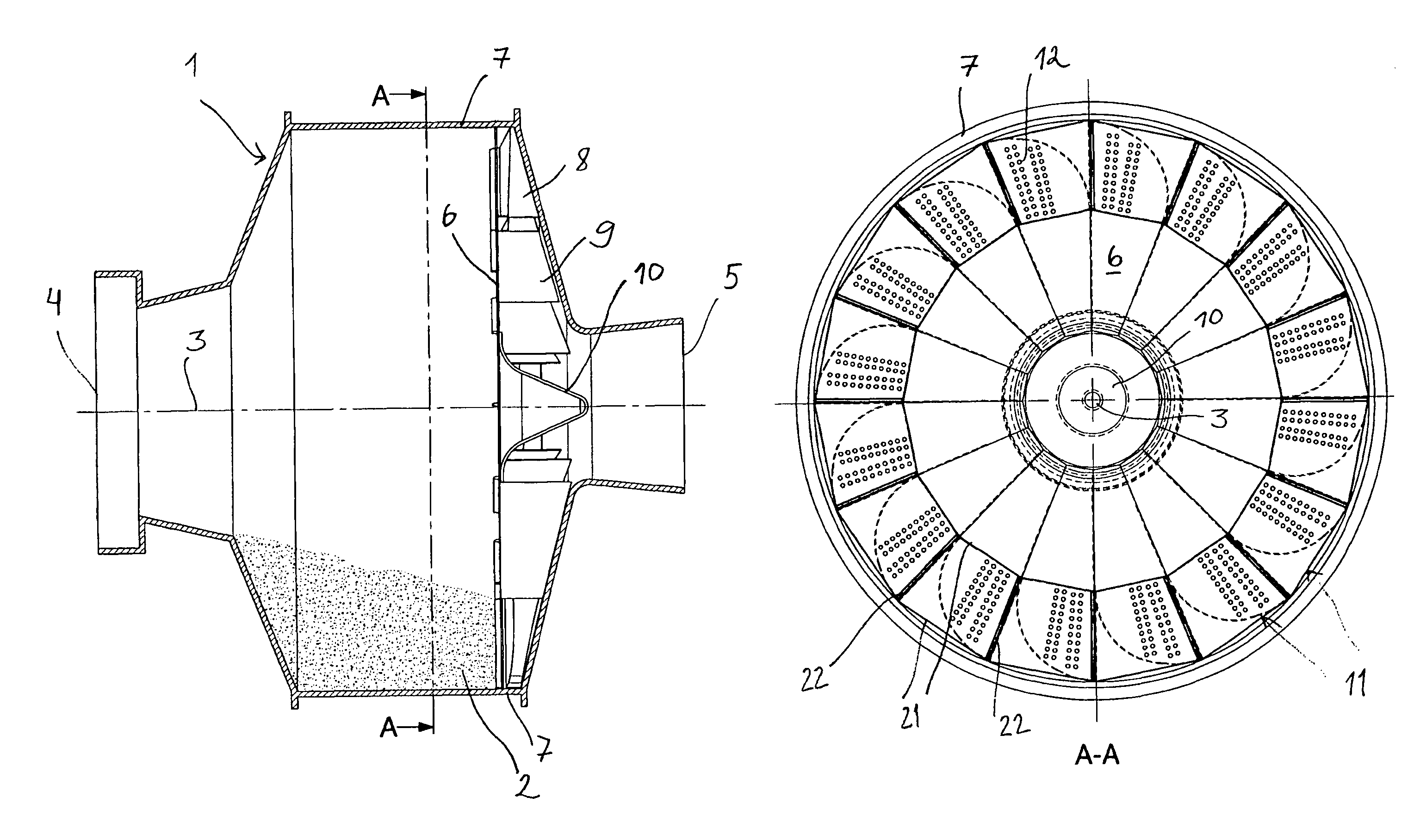
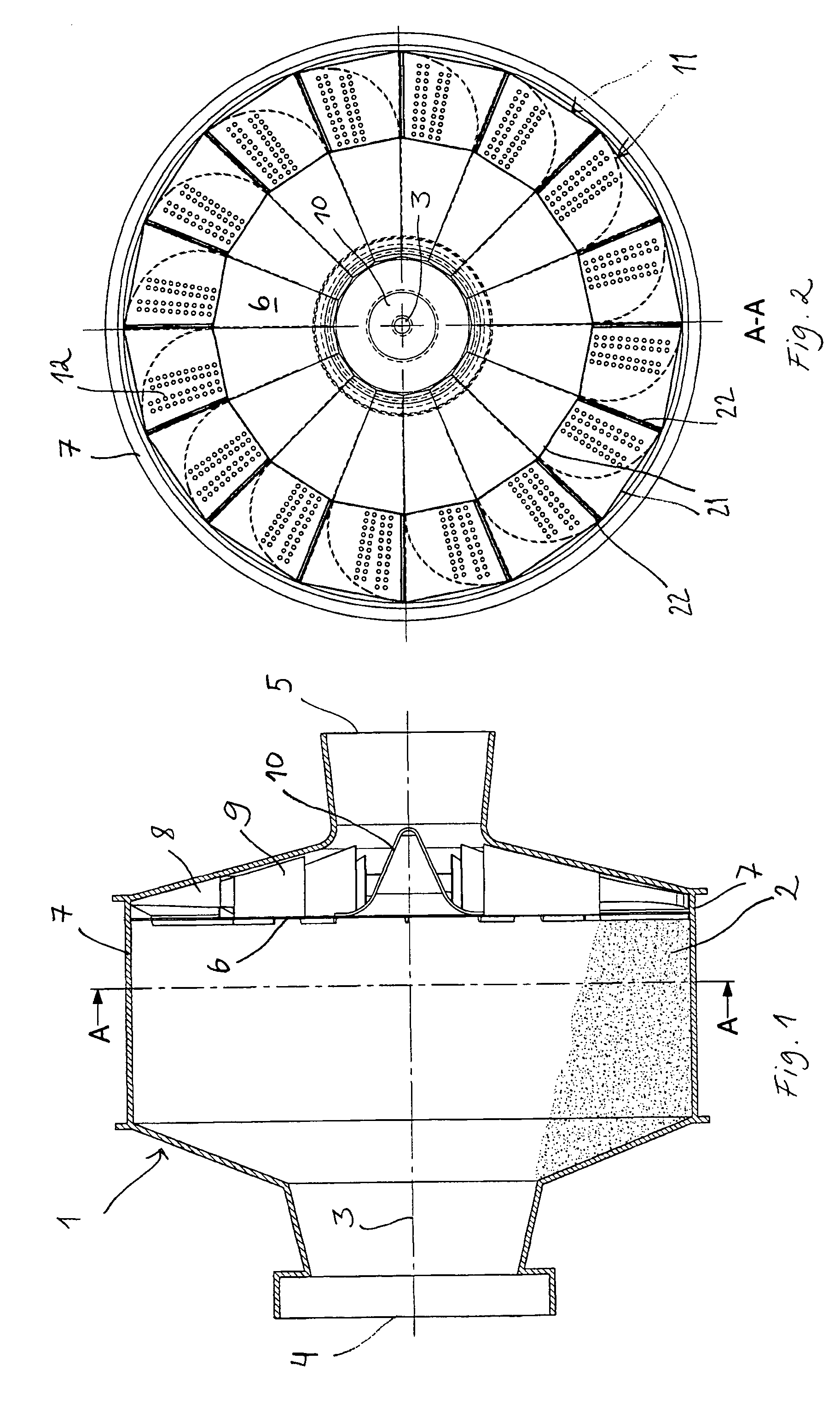
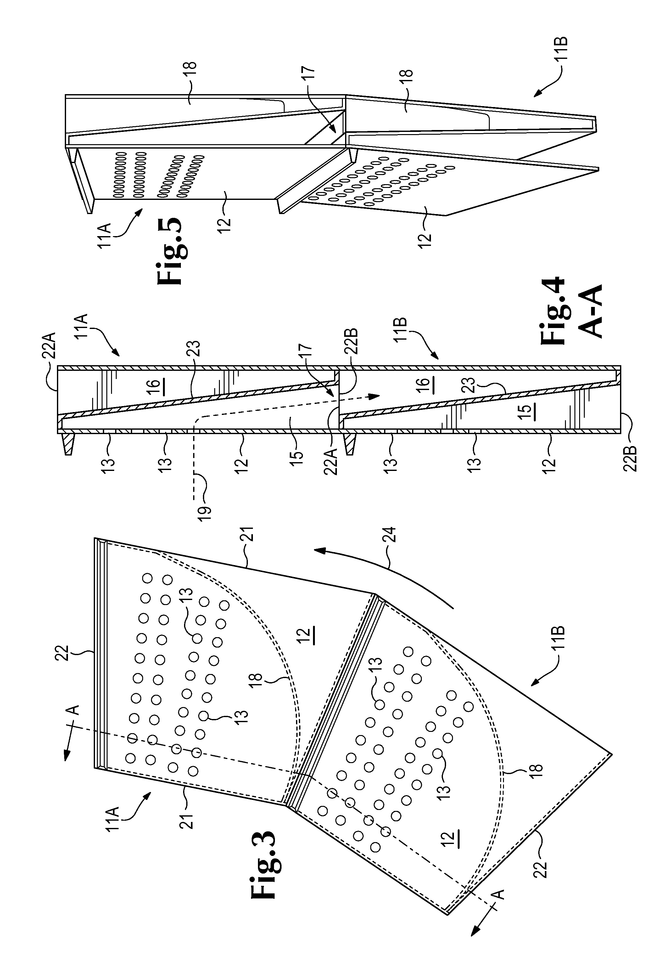
[0026]FIGS. 1 and 2 show a rotary grinding mill 1 that contains material 2 to be ground therein with aid of grinding media. The mill 1 is arranged to rotate around a rotation axis 3. The mill is supported via supporting means (not shown) to a mechanical ground. The material 2 to be ground in the mill is fed into a grinding zone of the mill 1 through an inlet 4. Water is advantageously also fed into the mill 1 in order to create a wet grinding in the mill 1. Between the grinding zone and the discharge opening 5 of the mill 1, a framework 6 is installed inside the mill 1 and supported to the body 7 of the mill 1. The framework 6 is a supporting member for a pulp lifter assembly that comprises guide members 8, 9 and a discharge cone 10. The pulp lifter assembly directs the ground material from the grinding zone to the discharge opening 5 of the mill 1. As illustrated in FIG. 2, the pulp lifter assembly comprises several sequential pulp lifters 11. Each pulp lifter 11 is attached to a g...


PUM


Abstract

A pulp lifter for installation in a grinding mill has a leading edge and a trailing edge with respect to rotation of the mill and comprises a first wall bounding an interior space and a second wall dividing the interior space into first and second sections. The first wall includes a leading edge wall formed with an inlet opening providing access to the second section and an inner edge wall formed with an outlet opening for discharge of slurry from the second section. The second wall includes a guide that extends substantially from an outer end of the leading edge wall to a trailing end of the inner edge wall, and the first section of the interior space is open at the trailing edge of the pulp lifter.

Description

CROSS REFERENCE TO RELATED APPLICATION[0001]This application claims benefit of Provisional Application No. 60 / 691,989 filed Jun. 17, 2005, the entire disclosure of which is hereby incorporated by reference herein for all purposes.BACKGROUND OF THE INVENTION[0002]This invention relates to an apparatus for discharging material from a rotary mill that is used for grinding or comminution, and in which mill advantageously a grate and a pulp lifter are positioned upstream of a discharge opening in the proceeding direction of the material (i.e. the direction in which the material passes through the mill) and so installed in the interior of the mill that the grate and the pulp lifter are rotated with the rotation of the mill.[0003]Pulp lifters in a mill for grinding or comminution of material transport the slurry passing through the apertures in the associated grate into the discharge opening of the mill. International Publication WO 98 / 01226 relates to a pulp lifter for a grate discharge m...

Claims


Application Information

Patent Timeline
Patent Type & Authority Patents(United States)
IPC IPC(8): B02C17/14
CPCB02C17/1855B02C17/1825
Inventor LATCHIREDDI, SANJEEVA R.
Owner METSO OUTOTEC (FINLAND) OY
Why Eureka
Try Eureka