Eccentric-based caster adjustment apparatus

a technology of caster adjustment and eccentric base, which is applied in the direction of steering parts, suspension arms with a pliable pivot, vehicle components, etc., can solve the problems of affecting camber, difficult to determine just what adjustment, and inability of caster to work, so as to ensure the maintenance of camber, easy to adjust caster, and small expenditure of time and effor

Inactive Publication Date: 2009-08-04
HOUSER JOHN ABBOTT +1
View PDF20 Cites 19 Cited by
  • Summary
  • Abstract
  • Description
  • Claims
  • Application Information

AI Technical Summary

Benefits of technology

[0011]The eccentric ball joint stud support is retained in position by a circular retainer disc which rotates with the stud support and is configured with a retainer opening corresponding with the eccentric opening such that the threaded stud may pass through it and receive a locking nut. Advantageously, the locking nut need not be removed from the stud to carry out a caster adjustment. This locking feature assures the maintenance of camber when adjusting caster. Because each caster orientation is associated with a visible indicia such as a number, the operator of the vehicle may record optimum caster for each racing venue and readily adjust caster with little expenditure of time and effort.

Problems solved by technology

While camber can be tuned by bolt and nut adjustment at the upper ball joint, caster cannot.
Unfortunately, that form of adjustment also affects camber.
Assuming adjustments have been made for given racing venue, the inherent structure of the front wheel suspensions are such that it is difficult to determine just what adjustment has been made as the vehicle is tuned for a next racing venue.

Method used


Image

  • Eccentric-based caster adjustment apparatus
  • Eccentric-based caster adjustment apparatus
  • Eccentric-based caster adjustment apparatus

Examples


Embodiment Construction

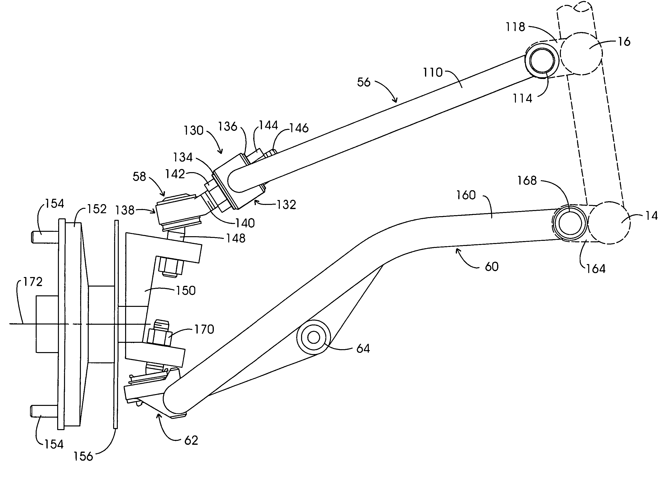
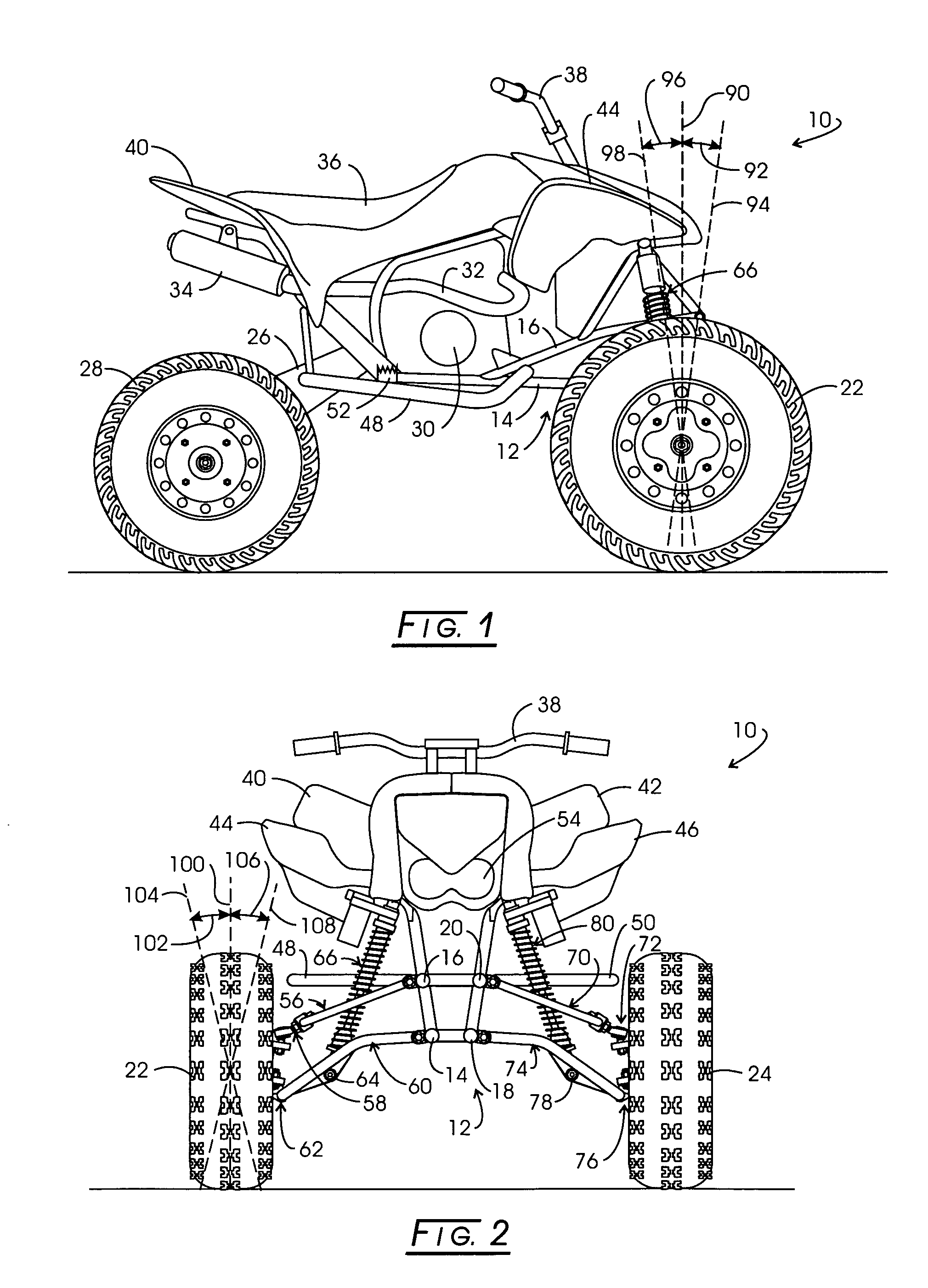
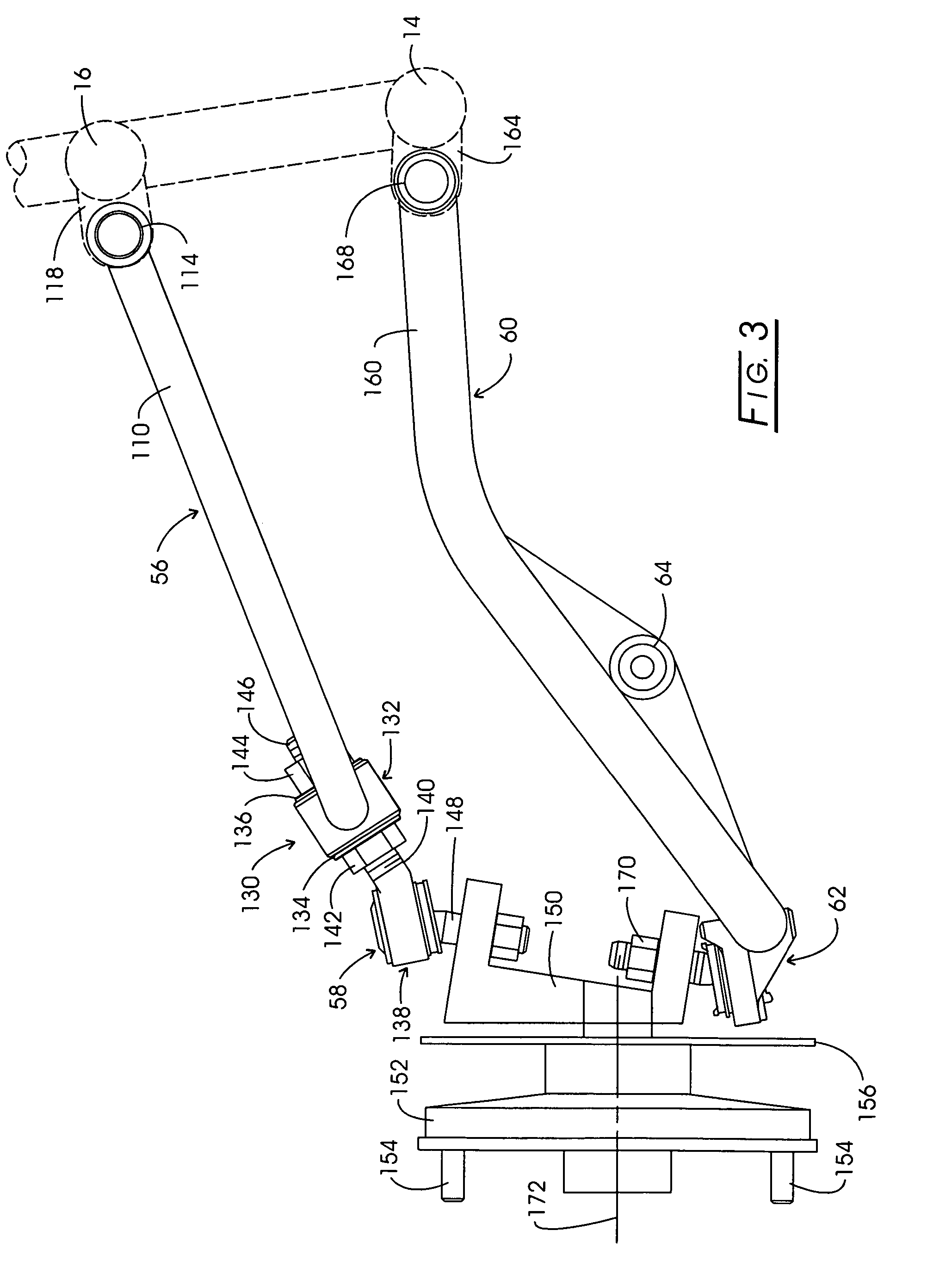
[0026]Referring to FIG. 1, a quad sport-type all terrain vehicle (ATV) is represented generally at 10. Vehicle 10 is configured with a tubular frame represented generally at 12, one component of which is represented at 14 and another such component is seen at 16. Components 14 and 16 are at the right side of vehicle 10. Looking additionally at FIG. 2, complimentary frame components are seen respectively at 18 and 20 as are associated with the left side of the vehicle. These figures reveal right and left forward wheels 22 and 24 which are freely rotatable. A rearwardly directed swing arm 26 (FIG. 1) supports a driven axle along with right and left rear drive wheels, the right drive wheel being seen at 28. The diameter of wheels as at 28 is less than that of the front wheels but generally will exhibit a wider geometry.

[0027]Frame 12 further supports a motor represented schematically at 30 in FIG. 1. Motor 30 incorporates an exhaust pipe 32 which extends rearwardly to a muffler 34. Abo...


PUM


Abstract

Apparatus for adjusting the caster of the steering wheels of an all terrain vehicle. An eccentric threaded stud support is adjustively rotatable to position the eccentrically retained stud at a plurality of caster angle defining orientations extending from zero caster negatively or positively. Perceptible indicia identifies each caster incremental location.

Description

CROSS-REFERENCE TO RELATED APPLICATIONSSTATEMENT REGARDING FEDERALLY SPONSORED RESEARCH[0001]Not applicable.BACKGROUND OF THE INVENTION[0002]In 1967 the American counterpart to a global motorcycle manufacturer requested the development of a vehicle that its dealers could sell during the winter season of slackening motorcycle sales. The result was the introduction of a three-wheeled all terrain vehicle (ATV) which debuted in 1970. This original ATV exhibited a tricycle geometry and employed a seven horsepower motorcycle engine to drive two rear twenty-two inch low pressure tires through a dual-range, four-speed gear box with an automatic clutch. The machines handled snow, mud and various slippery conditions which a motorcycle couldn't.[0003]Further development optimized tire and chassis design. While then primarily a recreational device, farmers saw substantial utility in the ATV. In this regard, a farm tractor costs exponentially more than an ATV and a typical ATV utilized 8% of the...

Claims


Application Information

Patent Timeline
Patent Type & Authority Patents(United States)
IPC IPC(8): B62D17/00
CPCB60G7/008B62K5/08B62D17/00B62K5/01B60G2200/144B60G2200/464B60G2204/148B60G2204/416B60G2204/44B60G2204/61B60G2206/124B60G2204/42
Inventor HOUSER, JOHN ABBOTTHOUSER, JEFFREY DAVID
Owner HOUSER JOHN ABBOTT
Why Eureka
Try Eureka