
Eye-safe near infra-red imaging illumination method and system

a near infrared and imaging illumination technology, applied in the field of near infrared imaging illumination, can solve problems such as damage to the retina, and achieve the effect of avoiding illuminating the subject, limiting the safe level for a long tim

Active Publication Date: 2009-08-04
GENTEX CORP
View PDF6 Cites 23 Cited by
  • Summary
  • Abstract
  • Description
  • Claims
  • Application Information

AI Technical Summary

Benefits of technology

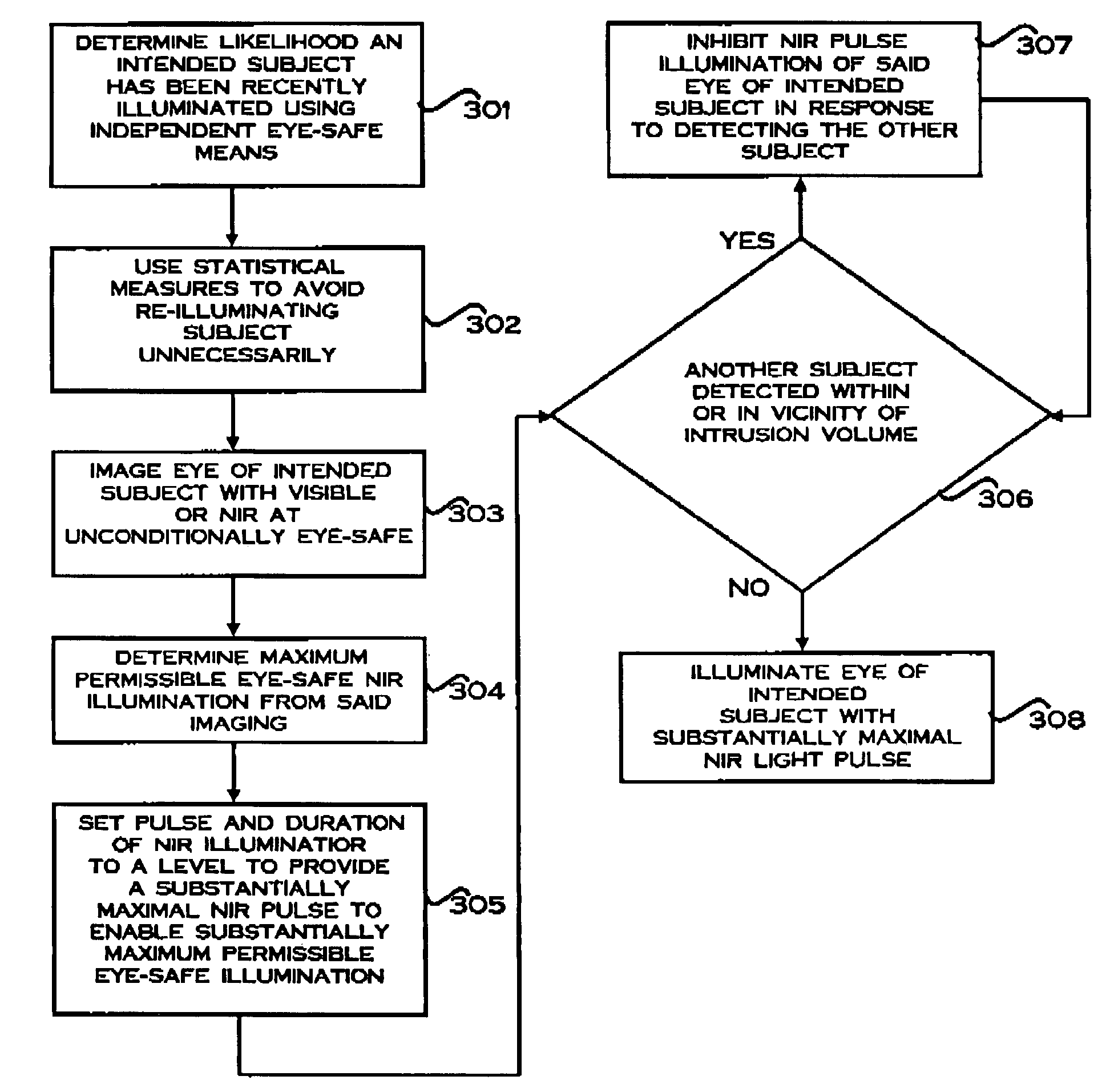
The present invention relates to a method for eye-safe near infra-red (NIR) optical imaging illumination. The method involves imaging an eye of an intended subject with NIR light at an unconditionally eye-safe illumination level, and determining the maximum permissible eye-safe NIR illumination that can be applied to the eye. The method can also involve illuminating the eye with at least one substantially maximal NIR light pulse, which has a pulse intensity and duration selected to provide the maximum permissible eye-safe NIR illumination. The invention can also include detecting another subject who may have an eye at risk, and avoiding illuminating the intended subject with the NIR light in response to detecting the potential for harm to an eye of the another subject. The technical effects of the invention include providing a safer and more effective method for eye-safe NIR optical imaging illumination.

Problems solved by technology

NIR light pulses above a certain intensity or total energy can damage the retina, particularly the cells of the fovea which provide acute central vision.

Method used


Image

  • Eye-safe near infra-red imaging illumination method and system
  • Eye-safe near infra-red imaging illumination method and system
  • Eye-safe near infra-red imaging illumination method and system

Examples


Embodiment Construction

[0031]The particular values and configurations discussed in these non-limiting examples can be varied and are cited merely to illustrate at least one embodiment of the present invention and are not intended to limit the scope of the invention.

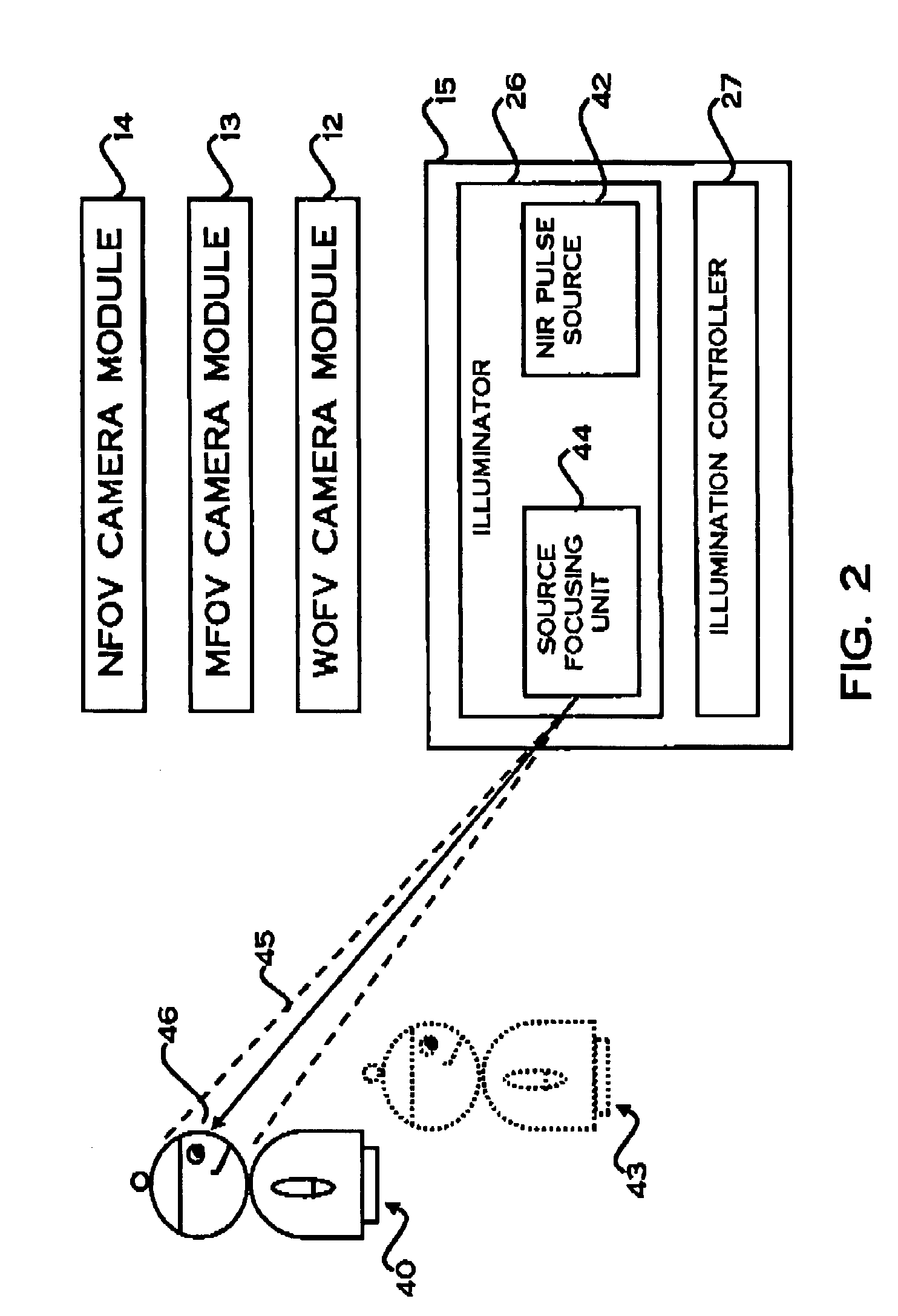
[0032]The illustrative embodiment provides an approach to eye-safe near IR imaging which reduces the inherent noise within captured images of the eyes and allows the distance at which the eyes can be imaged to be substantially maximized. The approach can also ensure that subjects which are in the vicinity of the imaging illumination are prevented from being illuminated with high intensity NIR illumination and can further ensure that re-illumination of subjects is controlled so that accumulated NIR illumination received by the subjects' eyes is constrained to long-term safe levels.

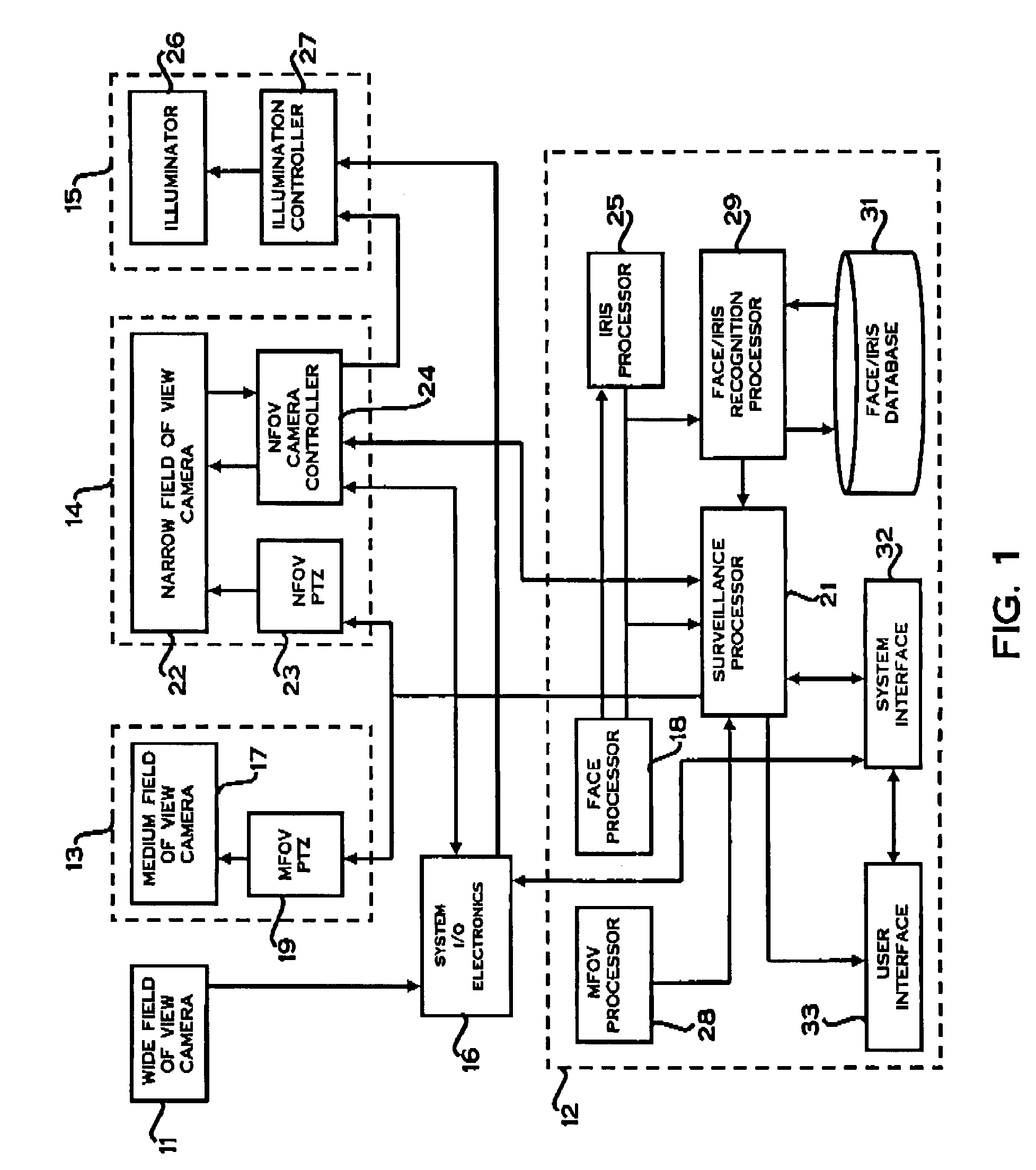
[0033]Reference will initially be made to an NIR optical imaging system of FIG. 1 of the accompanying drawings which can be used to implement the method for eye-safe N...


PUM


Abstract

A method and system for eye-safe near infra-red (NIR) optical imaging illumination. An eye of an intended subject are imaged with visible light or NIR light at an unconditionally eye-safe illumination level and the maximum permissible eye-safe NIR illumination that can be applied to the eye is determined from the captured images. The eye of the intended subject can then be illuminated with at least one substantially maximal NIR light pulse having a pulse intensity and duration selected to provide the substantially maximum permissible eye-safe NIR illumination intensity at the eye. NIR light pulse illumination can be inhibited in response to detection of other subjects either within the vicinity of a volume extending between an NIR illuminator illuminating the eye and the intended subject. The likelihood that an intended subject has been recently illuminated can also be determined and statistical measures can be used to avoid re-illuminating subject unnecessarily.

Description

FEDERALLY-SPONSORED RESEARCH AND DEVELOPMENT[0001]This invention was made with Government Support under a Biometric COE contract funded by the U.S. Government. As such, the U.S. Government has certain rights in this invention.TECHNICAL FIELD[0002]The embodiments relates to near infra-red (NIR) imaging illumination and, more particularly, to methods for eye-safe NIR imaging illumination for recognition systems, especially iris recognition systems. Embodiments also relate to NIR imaging illumination systems, such as eye-safe combined face and iris recognition systems.BACKGROUND[0003]Imaging human irises for biometric identification purposes usually requires that the subject's iris be illuminated in near-infrared (NIR) wavelengths just beyond those of visible red light. Bright light at such wavelengths is not visible and does not trigger an aversion response, such as pupil narrowing, blinking or averted gaze. Despite humans being relatively unaware of such illumination, it passes throu...

Claims


Application Information

Patent Timeline
Patent Type & Authority Patents(United States)
IPC IPC(8): A61B3/00A61B3/10G06K9/00G06V10/141G06V10/143
CPCG06K9/00604G06K9/2027G06K9/2018G06V40/19G06V10/141G06V10/143
Inventor PHINNEY, THOMAS L.JELINEK, JAN
Owner GENTEX CORP
Learn More