Drive hub unit for a wind power generator

a technology for wind power generators and hub units, which is applied in the direction of electric generator control, machine/engines, gears, etc., can solve the problems of detrimental effect of gear tooth engagemen

Inactive Publication Date: 2008-08-28
SCHULER PRESSEN GMBH & CO KG
View PDF16 Cites 36 Cited by
  • Summary
  • Abstract
  • Description
  • Claims
  • Application Information

AI Technical Summary

Benefits of technology

[0010]A transmission-hub unit (1) for a wind energy installation includes a a transmission (3) including a single piece rotatably supported transmission part (12, 27) which comprises the input gear wheel (11) of the transmission (3) as well as the blade-hub (2). Preferably, only two radial bearings (16, 18) for th

Problems solved by technology

This concept facilitates a minimization of the tilt movements of the transmissi

Method used


Image

  • Drive hub unit for a wind power generator
  • Drive hub unit for a wind power generator
  • Drive hub unit for a wind power generator

Examples


Embodiment Construction

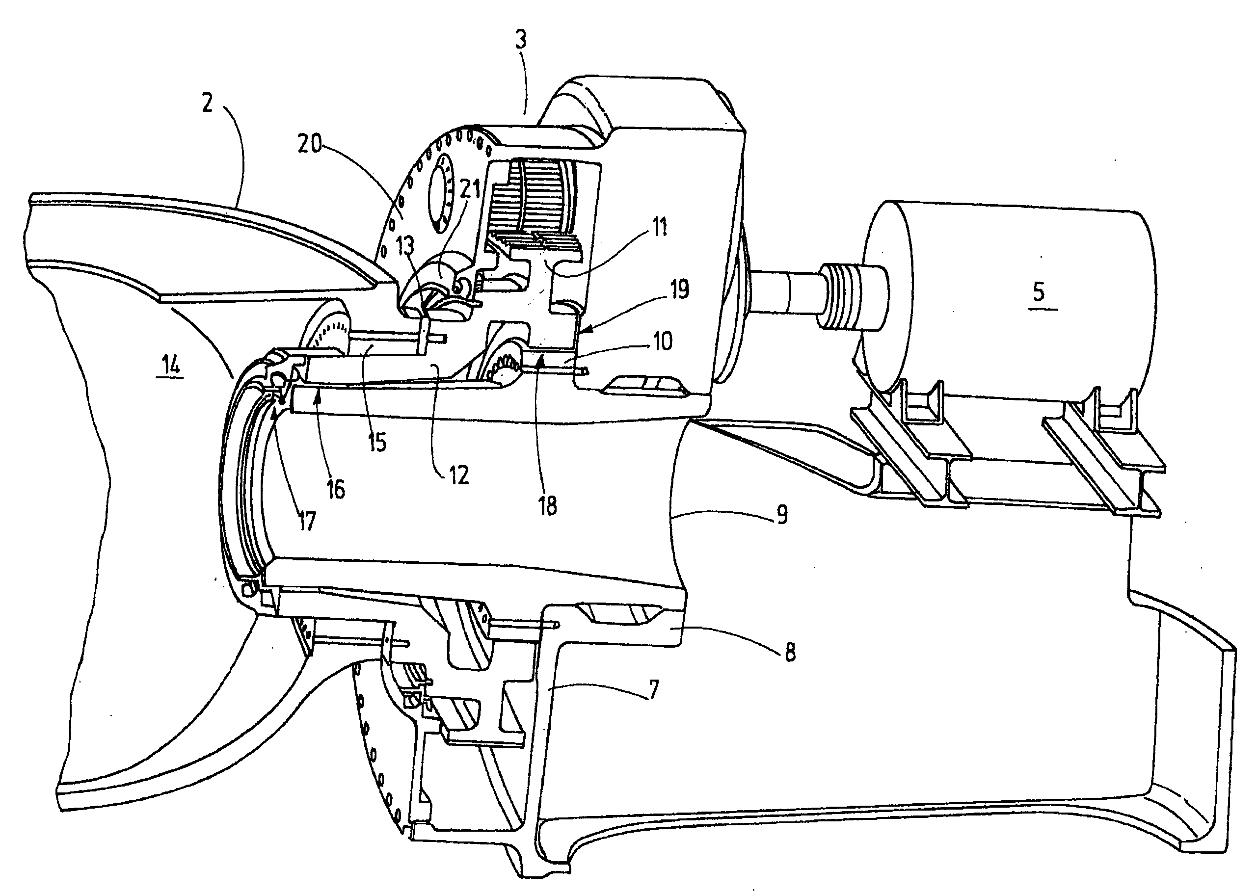
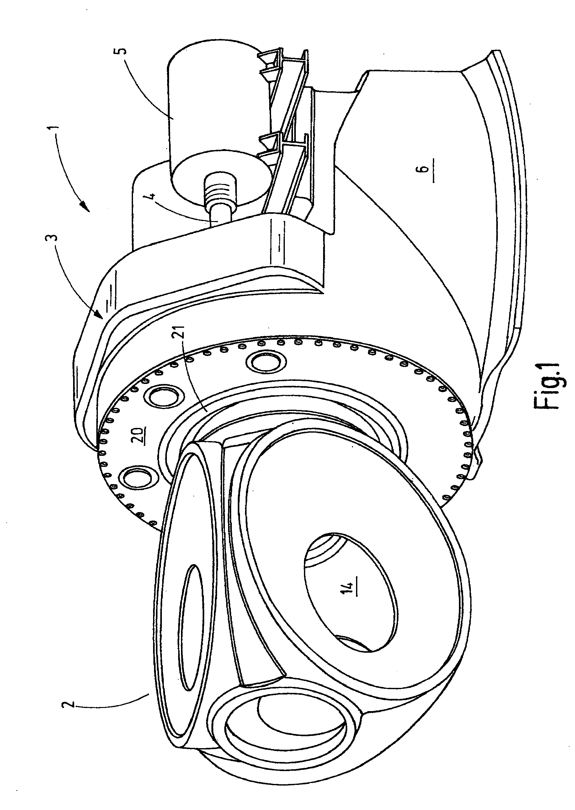
[0023]FIG. 1 shows a transmission-hub unit 1 of a wind energy turbine. The transmission-hub unit 1 is mounted in a nacelle, for example, on top of a tower. It carries on its blade-hub 2 which is in the form of a hollow housing several, for example, three rotor blades, not shown, by which the blade-hub 2 is rotated. The rotation of the blade-hub 2 is converted by way of a transmission 3 to a rapid rotation of the drive shaft 4 of at least one electric generator 5. FIG. 1 is not according to scale.

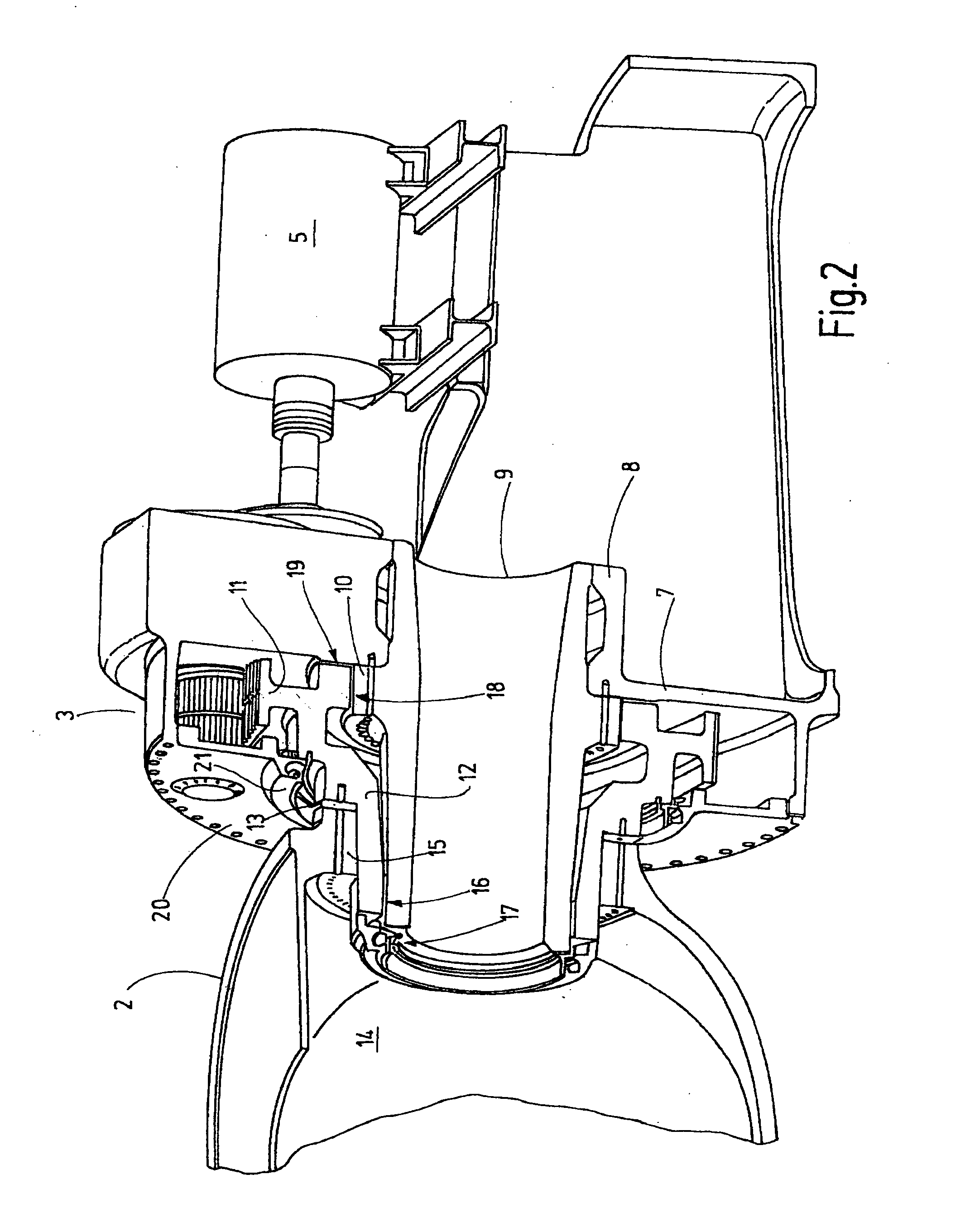
[0024]The transmission-hub unit 1 includes a support stand 6 which is part of the nacelle or which is connected thereto. It is supported so as to be rotatable or pivotable about a horizontal axis. The stand 6 is provided with an essentially vertical front wall 7 as shown in FIG. 2 and which forms a support structure for supporting a tubular carrier or sleeve 9. The sleeve 9 is disposed with one end in the essentially cylindrical seal 8 and projects therefrom in a cantilevered fashion support...


PUM


Abstract

A transmission-hub unit (1) for a wind energy installation includes transmission (3) including a single piece rotatably supported transmission part (12, 27) which comprises the input gear wheel (1 1) of the transmission (3) as well as the blade-hub (2). Preferably, only two radial bearings (16, 18) for the support of the blade-hub (2) and the gear wheel (11) are provided. Additionally, axial bearings may be provided. A particularly compact, short, and light-weight arrangement for the transmission (3) and the blade-hub (2) is obtained thereby. The concept is particularly suitable for large wind energy installations.

Description

CROSS-REFERENCE TO RELATED APPLICATION [0001]The application claims the priority benefits of German Application No. 10 2007 008 758.8 filed Feb. 22, 2007.BACKGROUND OF THE INVENTION [0002]The invention resides in a drive hub unit of a wind power generator installation.[0003]Wind power or wind energy installations generally include a rotor with at least one, generally however two or three, rotor blades which are supported so as to be rotatable about a horizontal axis and which drives a generator. Herein, basically two different concepts are pursued. A first concept does not require a transmission. The generator is firmly connected to the rotor for rotation therewith. Another very popular concept resides in the provision of a transmission between the rotor and the generator. The generator is operated at a comparatively high speed whereby it can be smaller and lighter and it requires a relatively small number of poles.[0004]DE 10 2004 036 005 A1, for example, discloses such a concept w...

Claims


Application Information

Patent Timeline
IPC IPC(8): F16H57/08F16C21/00F16C19/02F16C19/00F03D9/00
CPCF03D11/0008F03D11/02F05B2240/52F05B2240/54Y02E10/722F05B2260/40311F16C2300/14F16H1/22F16H37/065F05B2240/61F03D15/00F03D80/70Y02E10/72F03D15/10
Inventor FAHRENBACH, JURGENDANGELMAYR, ANDREASHOFELE, HANSSCHADE, VOLKER
Owner SCHULER PRESSEN GMBH & CO KG
Why Eureka
Try Eureka