Double Hybrid Heat Pumps and Systems and Methods of Use and Operations

a heat pump and hybrid technology, applied in the field of heat pumps, can solve the problems of prohibitively high cost of conversion of homes heated by hot water, limited retrofitting, and high cost of typical homeowners, and achieve the effects of reducing the cost of installation, and reducing the cost of maintenan

Active Publication Date: 2022-11-03
DESMARAIS MATTHEW
View PDF2 Cites 0 Cited by
  • Summary
  • Abstract
  • Description
  • Claims
  • Application Information

AI Technical Summary

Benefits of technology

[0013]In various embodiments, the water heated by the condensing heat exchanger is provided to one or both of 1) a hot water tank for storage or for use as domestic hot water and 2) a hydronic heating loop that may serve a variety of uses. For example, in a hot water heating system including a boiler, in the heating mode, the double hybrid heat pump may make hot water for use as either domestic hot water or hydronic hot water to as a replacement for the boiler for heating, as well as providing hot air from the inside refrigerant to air heat exchanger for heating. Whereas, in the cooling mode, the double hybrid heat pump may provide hot water for domestic hot water and cool air for air conditioning. While in cooling mode, the first condenser shall first absorb the heat rejected by the compressor and any remaining heat will be rejected outside the system. In cooling mode, if the conditions permit, the system can prioritize condensing for producing useful hot water and then use a favorable temperature difference to further subcool the refrigerant before it reaches the thermal expansion valve, increasing the net efficiency of the system greatly.
[0014]The double hybrid heat pump may be used to eliminate many external components, complicated controls, and the huge amount of labor required to retrofit a home from an existing hot water heating system to a ground or water source heat pump. It can be installed with minimal training and has built-in features that limit the risk to the contractor. For example, in a hot water heating system, the present invention may be used to eliminate a domestic hot water pre-heat tank, 1 heat pump, 1 flow center, 1 HDPE manifold, 1 circulator, domestic hot water piping, hydronic fan coils and extra zone controls which result in substantial installation and operational savings.
[0015]Accordingly, the present disclosure addresses the continuing need for HVAC systems with improved cost and performance.

Problems solved by technology

Presently, converting homes that are heated by hot water is prohibitively expensive for the average homeowner.
Retrofitting these homes are limited to several expensive options, which include for example:1. Replacing every radiator or baseboard with larger radiators or panel radiators or baseboards that can operate at low heating supply temperatures (between 110-120 degrees)2. Replacing the hot water system with a forced hot air system,3. Using two heat pumps to provide hot air and water at the same time, or4. Adding several hydronic air handlers and ductwork to supplement the heat output from the existing heating system.
The cost of these options can range from $70,000-$100,000, which is far too expensive for a typical homeowner.
Additionally, the level of complexity in these retrofits can make these jobs undesirable to installers as well.
The uptake of heat pump systems in the commercial and industrial markets has been slower than residential due, at least in part, to the additional complexity and requirements of these systems, such as the need for chilled water, etc.

Method used


Image

  • Double Hybrid Heat Pumps and Systems and Methods of Use and Operations
  • Double Hybrid Heat Pumps and Systems and Methods of Use and Operations
  • Double Hybrid Heat Pumps and Systems and Methods of Use and Operations

Examples


Embodiment Construction

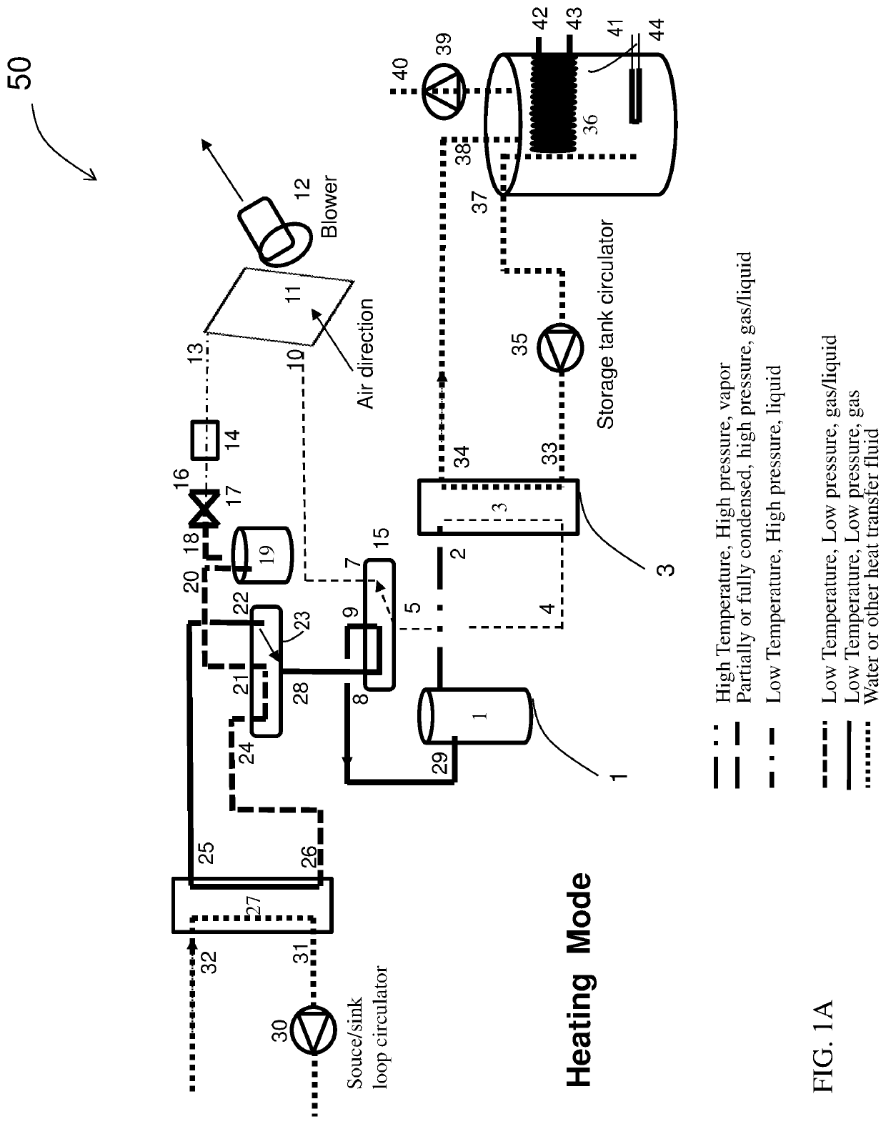
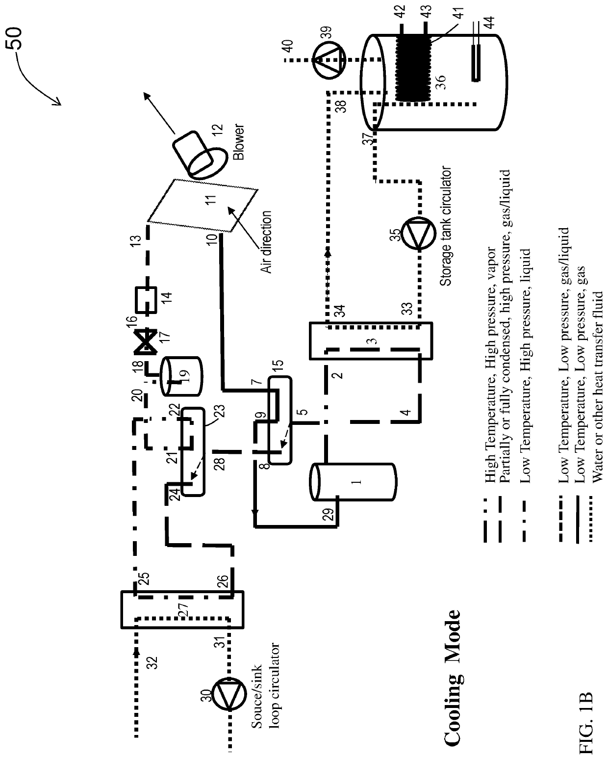
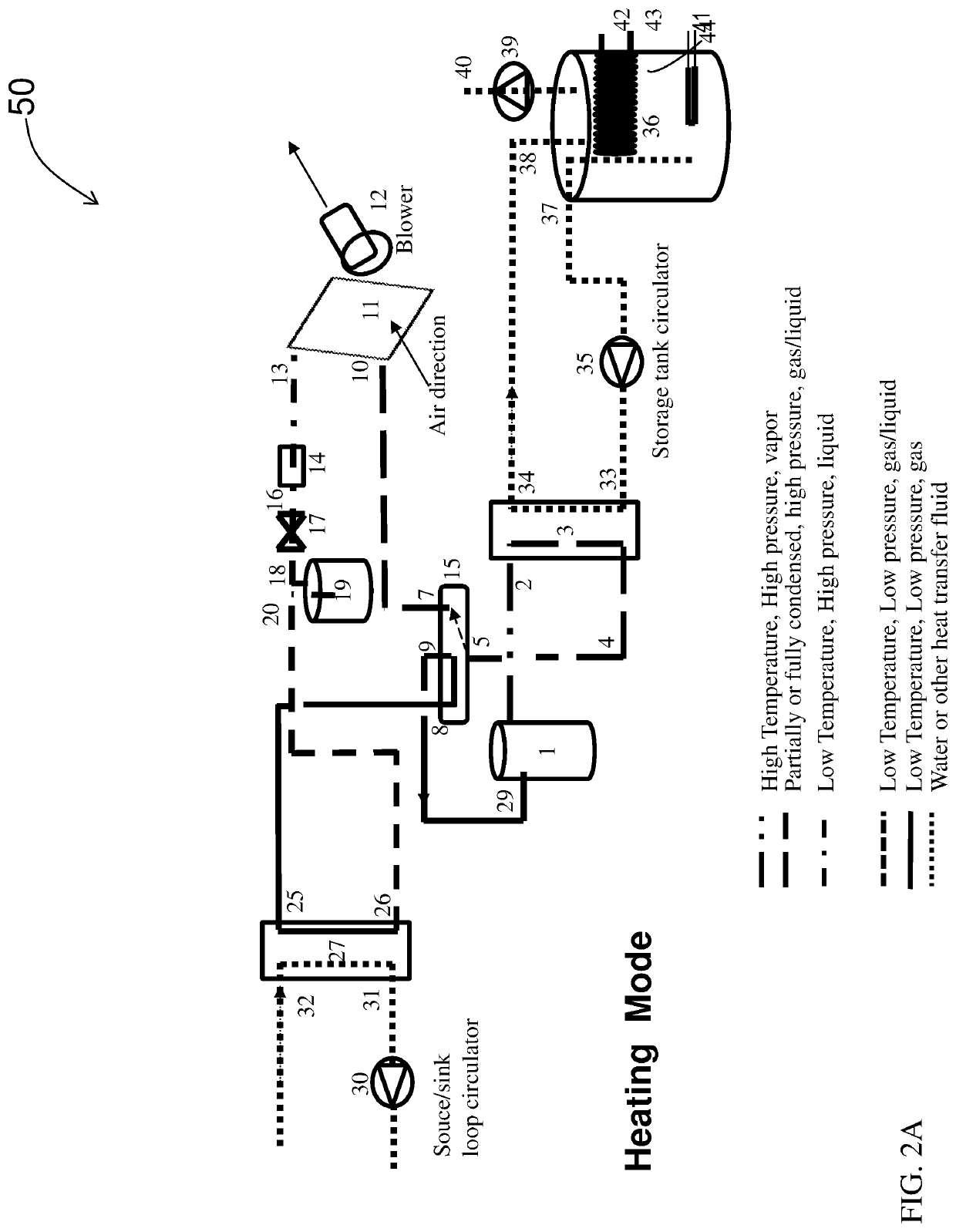
[0027]Systems 100, double hybrid heat pumps 50, and methods of use, operation, and control of the present invention may be employed in various heating and water supply solutions in a structure 200.

[0028]FIGS. 1A-2B depict exemplary schematic embodiments of double hybrid heat pumps 50. A compressor 1 receives at an inlet and then compresses a low-pressure vapor phase refrigerant to high-pressure vapor phase refrigerant, which passes through an outlet and is provided via connection 2 to an inlet to a refrigerant condensing heat exchanger 3. The refrigerant passes through the condensing heat exchanger 3 and is cooled by a first cooling fluid, which depending upon the application may be water or another fluid that may be used elsewhere. In various embodiments, the first cooling fluid may be circulated through the condensing heat exchanger 3 from a tank 36 using a storage tank circulator pump 35 via connections from 33, 34, 37 and 38 to remove heat from the high-pressure vapor phase refr...


PUM


Abstract

Double hybrid heat pumps, systems, and methods of operation that provide increased efficiency in both heating and cooling modes, heated water, and other advantages. The system includes a compressor for compressing low-pressure vapor phase refrigerant to high-pressure vapor phase refrigerant, a refrigerant condensing heat exchanger to heat water and cool the refrigerant to a high-pressure liquid refrigerant, which is provided to a refrigerant cooling heat exchanger in which any remaining high-pressure vapor phase refrigerant is condensed and the high-pressure liquid refrigerant is further cooled. The high-pressure cooled liquid refrigerant is passed through an expansion valve to drop the pressure of the cooled liquid to yield a low-pressure cooled liquid refrigerant or low-pressure cooled two-phase refrigerant. The low-pressure cooled liquid or two-phase refrigerant is then evaporated in a refrigerant evaporating heat exchanger to produce the low-pressure vapor refrigerant that is returned to the compressor.

Description

CROSS-REFERENCE TO RELATED APPLICATIONS[0001]This application claims priority to and the benefit of U.S. Provisional Patent Application No. 63 / 183,615 filed on May 3, 2021, which is incorporated by reference in its entireties.STATEMENT REGARDING FEDERALLY SPONSORED RESEARCH OR DEVELOPMENT[0002]Not ApplicableBACKGROUND OF THE INVENTIONField of the Invention[0003]The present invention generally relates to heat pumps. More specifically, the invention relates to hybrid heat pumps that may be used in combination with hot water and forced air systems for heating and domestic water supply and cooling systems.Background Art[0004]Residential, commercial and industrial heat pump systems are a growing market worldwide because they can be high efficiency and may be used to replace less efficient heating and cooling systems. The growth in heat pumps has been primarily in new homes or existing residences that have forced hot air heating systems. Presently, converting homes that are heated by hot ...

Claims


Application Information

Patent Timeline
Patent Type & Authority Applications(United States)
IPC IPC(8): F25B30/02F25B13/00F24H4/04
CPCF25B30/02F25B13/00F24H4/04F25B2339/047F25B25/005F25B2313/02742
Inventor DESMARAIS, MATTHEW
Owner DESMARAIS MATTHEW
Why Eureka
Try Eureka