
Method For Determining A Change In A Communication Signal And Using This Information To Improve SPS Signal Reception And Processing

a communication signal and information technology, applied in the field of determining a change in a communication signal, can solve the problems of inconvenient use, more time-consuming acquisition/search process, and techniques in the prior ar

Inactive Publication Date: 2008-07-03
QUALCOMM INC +1
View PDF38 Cites 1 Cited by
  • Summary
  • Abstract
  • Description
  • Claims
  • Application Information

AI Technical Summary

Benefits of technology

[0015]This invention has the advantage in that specialized external equipment used to determine motion, such as accelerometers, gyros, speedometers, etc. may be avoided. Such equipment may be expensive, require extensive installation, and may be unwieldy, especially for cost sensitive mobile consumer applications.

Problems solved by technology

The faster the velocity of the mobile SPS receiver, the more time consuming is the acquisition / search process.
These problems are caused by Doppler effects from the motion of the SPS receiver, which are compounded by the motion of the orbiting SPS satellites which are moving at high velocities.
Thus, the techniques in the prior art, while normally helpful for many situations, may not be advantageous when the SPS receiver is moving at high velocities.

Method used


Image

  • Method For Determining A Change In A Communication Signal And Using This Information To Improve SPS Signal Reception And Processing
  • Method For Determining A Change In A Communication Signal And Using This Information To Improve SPS Signal Reception And Processing
  • Method For Determining A Change In A Communication Signal And Using This Information To Improve SPS Signal Reception And Processing

Examples


Embodiment Construction

[0012]Methods and apparatuses signals are described for determining a change in a communication signal and using information related to this change in processing SPS. The following description and drawings are illustrative of the invention and are not to be construed as limiting the invention. In the following description, for purposes of explanation, numerous specific details are set forth in order to provide a thorough understanding of the present invention. It will be evident, however, to one skilled in the art that the present invention may be practiced without these specific details. In other instances, well known structures and devices are shown in block diagram form to facilitate explanation.

[0013]This invention, in one embodiment, deals with processing satellite positioning system (SPS) signals, such as GPS (Global Positioning System) signals from GPS satellites, when the SPS receiver is capable of undergoing movement. Under such conditions when the SPS receiver is moving, t...


PUM


Abstract

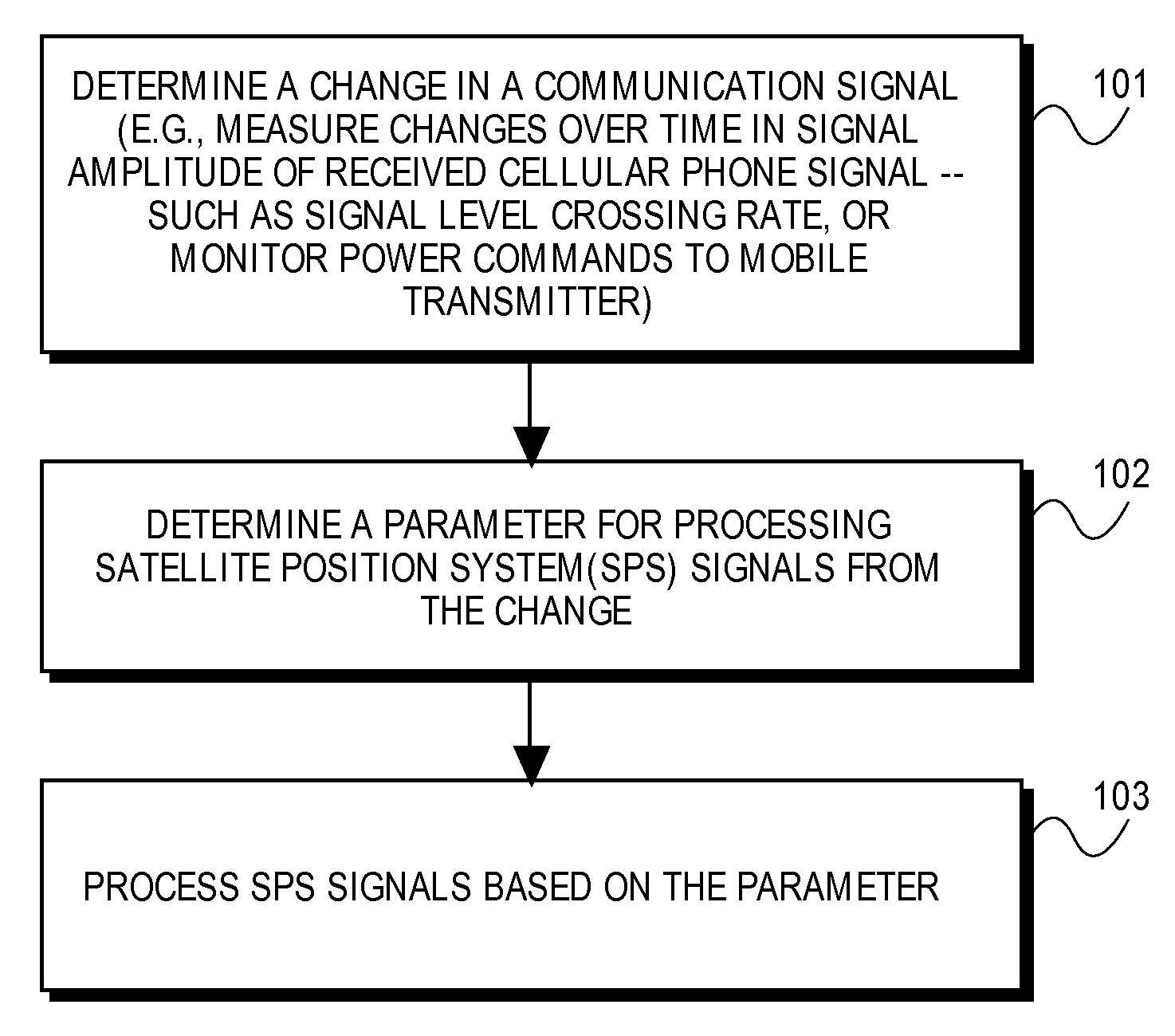
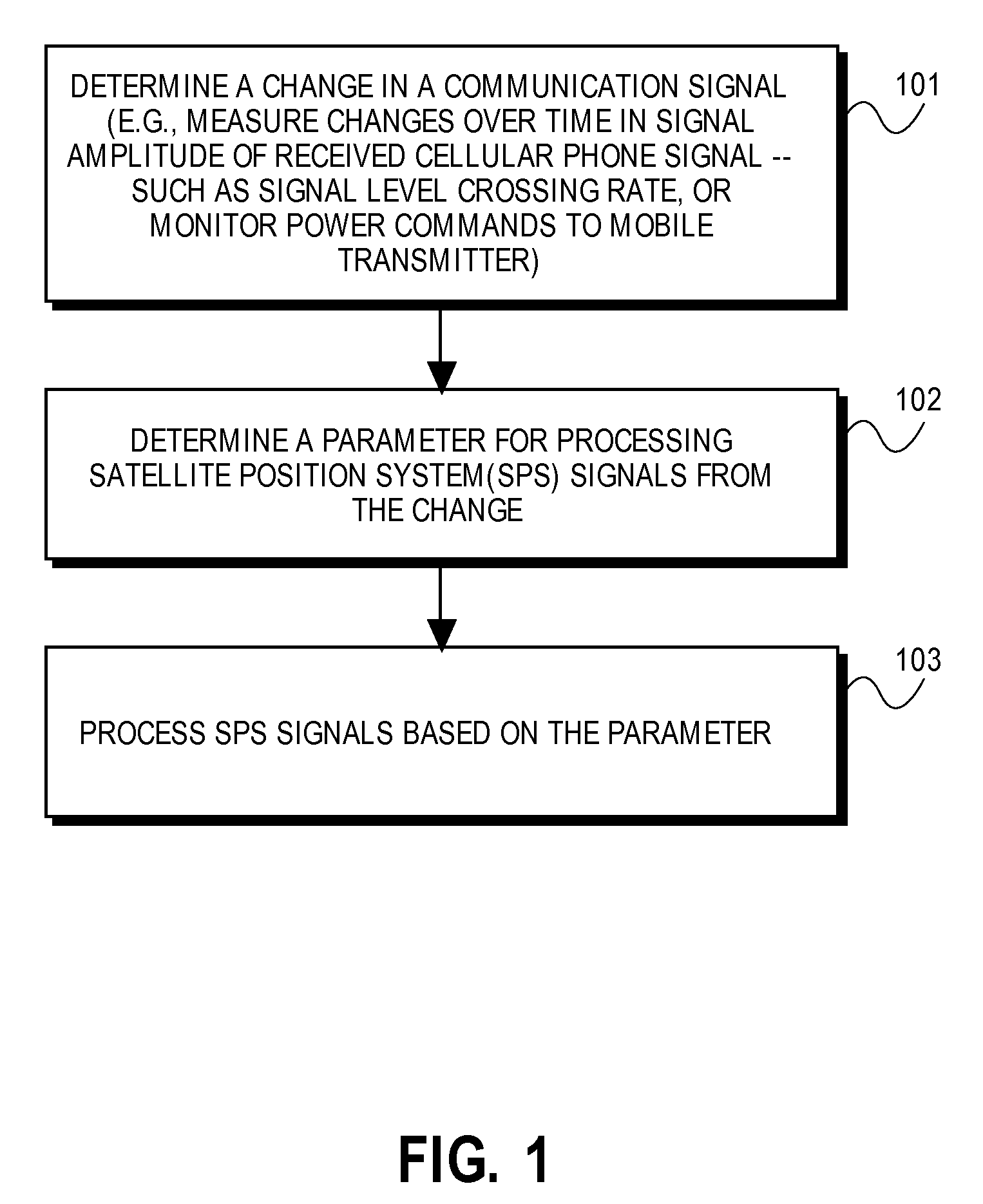
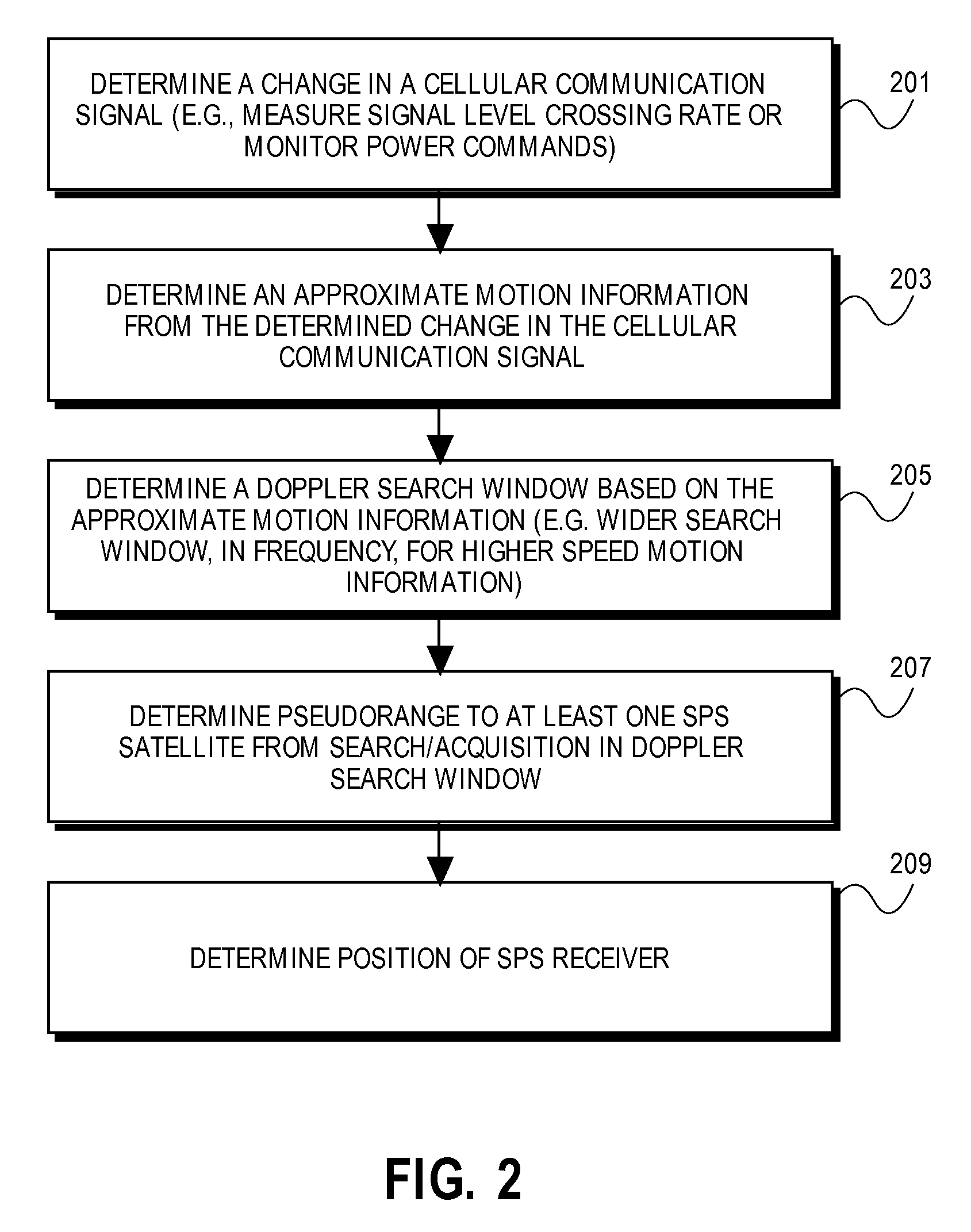
Methods and apparatuses for determining a position of a mobile satellite positioning system (SPS) receiver which is coupled to a communication receiver or transceiver. In one exemplary method, a change in a communication signal received by the communication receiver is determined. A parameter, based on the change, is determined, and SPS signals from SPS satellites are processed according to the parameter. According to further details of this method, the change involves the fluctuation of the level of the communication signal and the parameter is a motion information which specifies a frequency range for searching for SPS signals in the process of acquiring the SPS signals from SPS satellites. In an alternative embodiment the change in the communication signal is a change in the transmitted signal in response to power control commands. Apparatuses, such as a mobile communication system which includes an SPS receiver and a communication receiver, are also described.

Description

[0001]This application is a continuation of and hereby claims the benefit of the filing date of U.S. patent application Ser. No. 09 / 619,775, filed Jul. 20, 2000 by Norman F. Krasner and entitled “Method for Determining A Change in A Communication Signal And Using This Information To Improve SPS Signal Reception And Processing,” which is assigned to the assignee hereof.BACKGROUND[0002]It is known that the motion of mobile satellite position system (SPS) receivers (e.g. a Global Positioning System receiver), particularly while attempting to acquire SPS signals from an SPS satellite, will effect the position determination function of the SPS receiver. The faster the velocity of the mobile SPS receiver, the more time consuming is the acquisition / search process. Tracking (after acquisition) of SPS signals is also effected by faster velocities of the mobile SPS receiver. These problems are caused by Doppler effects from the motion of the SPS receiver, which are compounded by the motion of...

Claims


Application Information

Patent Timeline
Patent Type & Authority Applications(United States)
IPC IPC(8): G01S1/00G01P3/50G01S5/14G01P3/64G01S11/02G01S11/06G01S19/25G01S19/26H04B7/005H04B7/26H04B17/00H04W52/08H04W52/22
CPCG01P3/50G01P3/64G01S11/02G01S11/06H04B17/318G01S19/26H04W52/08H04W52/221H04W64/006G01S19/254
Inventor KRASNER, NORMAN F.
Owner QUALCOMM INC
Learn More