Apparatus and method for selectively determining a mode of operation

Inactive Publication Date: 2015-04-30
CROWCON DETECTION INSTR
View PDF1 Cites 1 Cited by
  • Summary
  • Abstract
  • Description
  • Claims
  • Application Information

AI Technical Summary

Benefits of technology

The present invention provides an apparatus that can automatically switch a detector to the correct mode of operation, without user intervention. This is done by detecting the detector's mode of operation upon installation, which saves time, labor, and cost. Additionally, the apparatus automatically switches to the source or sink mode based on the system to which the detector is being integrated, preventing errors in installation and the need for corrective action. Finally, since the apparatus does not require a record of the previous installation, it saves further time and is more cost efficient.

Problems solved by technology

Correct operation of a detector in either of sink or source modes typically requires user intervention to ensure that the correct detector mode is selected to match the power / control device setting, otherwise incorrect operation may result.
Such commissioning can be time consuming.
This may also be time consuming as records for each detector must be collected and maintained.
In industrial situations, where there may be many detectors connected to a control panel and / or where there are large numbers of detectors to deal with, it can be very time consuming to ensure correct operational configuration of the detectors.
Further, although once initially configured to operate in sink or source mode, it is likely that the mode of operation will not change for normal operation, industrial plant updates or upgrades may require that the detectors are reconfigured.
Manually updating detectors to ensure correct operation is time consuming, economically expensive and error prone.

Method used


Image

  • Apparatus and method for selectively determining a mode of operation
  • Apparatus and method for selectively determining a mode of operation
  • Apparatus and method for selectively determining a mode of operation

Examples


Embodiment Construction

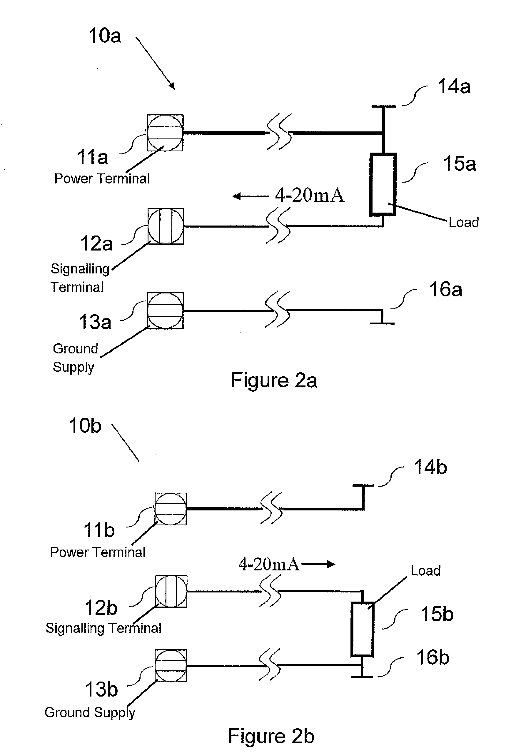
[0020]For three-wire connection detectors, such as gas detectors, operating with 4-20 mA signalling, the operating mode may either be source mode, whereby the detector signals by supplying a current to a control / power panel, or sink mode, whereby the detector signals by drawing current from a control / power panel.

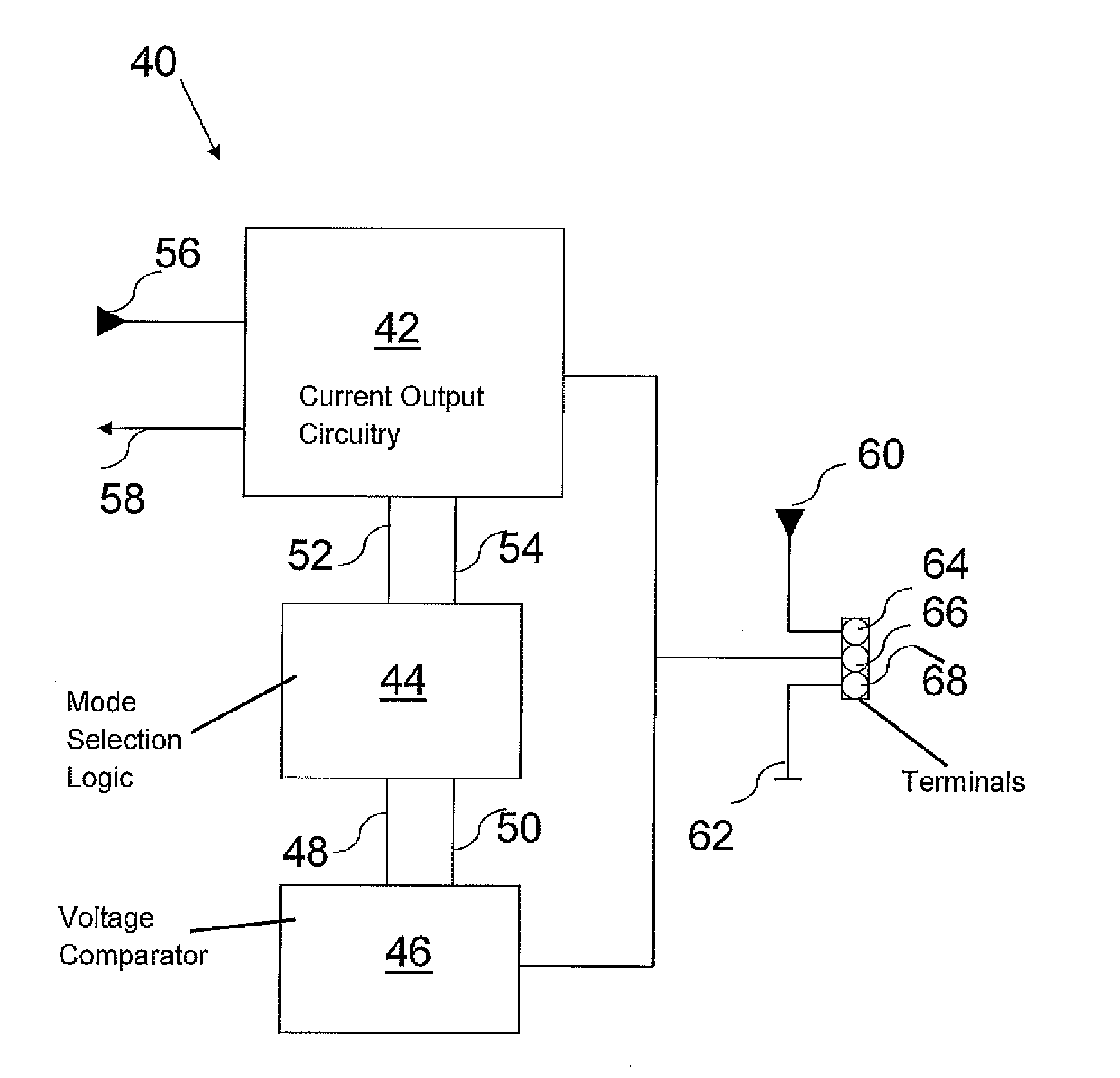
[0021]The potential operational modes of a detector are ordinarily implemented using variations in wiring viz. separate terminals for source and sink modes, or by using selection switches or selection links, which can be positioned to connect appropriate circuitry. In accordance with an aspect of the invention, apparatus is now described in reference to FIG. 1, whereby the apparatus provides advantages, including automatic determination of the appropriate operational mode and switching to provide operation in the appropriate operational mode.

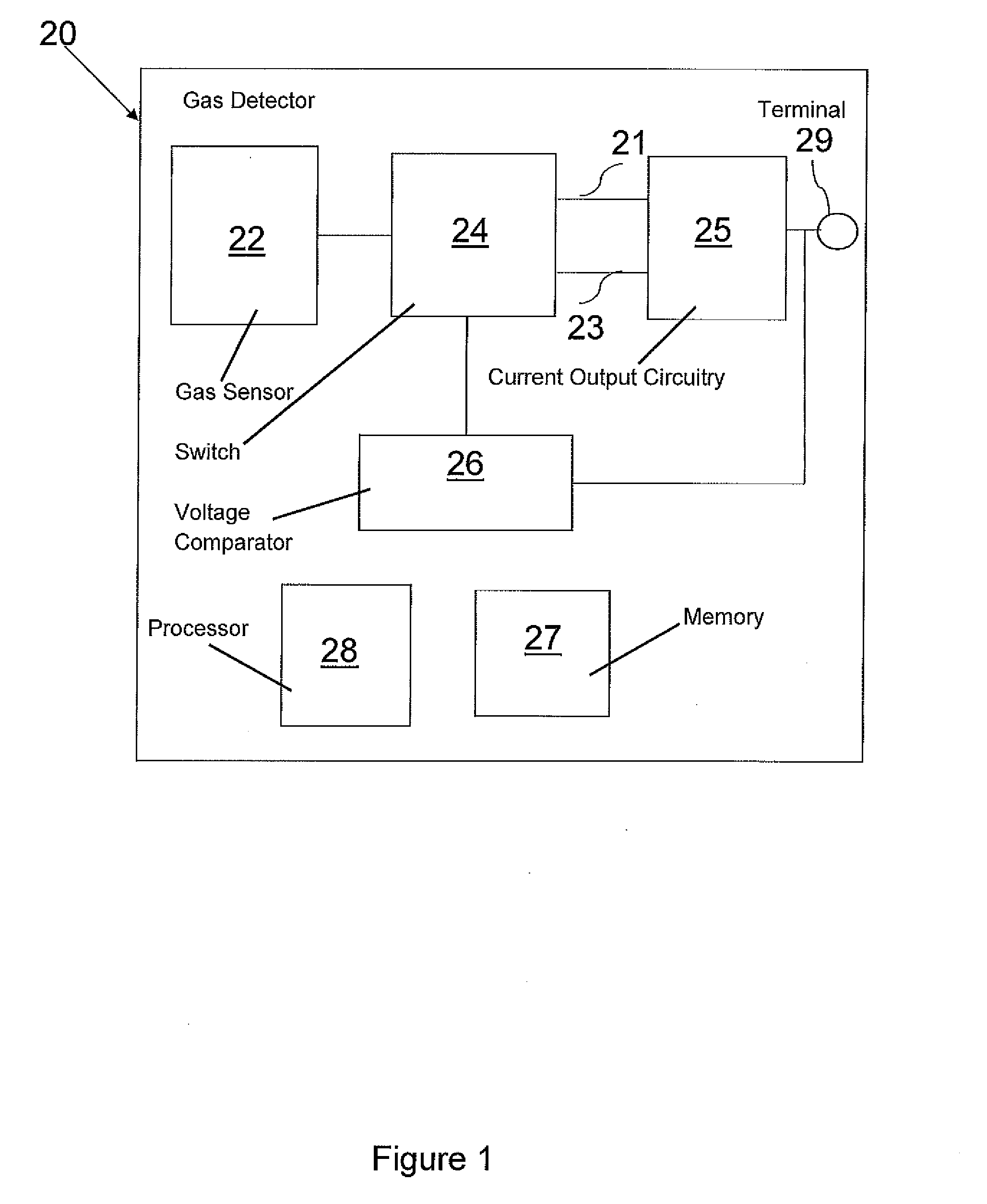
[0022]FIG. 1 is a diagram of apparatus 20 according to an example of the invention.

[0023]In preferred embodiments the apparatus 20 is a...


PUM


Abstract

An apparatus for selectively switching a mode of operation of a detector, the apparatus comprising a detector configured for connection to a signalling terminal, switching means for configuring the detector to operate in one of sink mode or source mode and a voltage comparator, wherein the apparatus is configured to selectively switch to operate in sink mode or source mode based on a comparison of a voltage from the signalling terminal received at the voltage comparator with a threshold voltage.

Description

CROSS-REFERENCE TO RELATED APPLICATION[0001]This application claims benefit of United Kingdom Patent Application Serial No. GB 1318987.3 filed on Oct. 28, 2013, the disclosure of which is hereby incorporated herein by reference in its entirety.FIELD OF INVENTION[0002]The present invention relates to a method and apparatus for automatically determining a mode of operation of a detector, in particular a gas detector.BACKGROUND TO THE INVENTION[0003]It is known to use 4-20 mA current signalling for the operation of detectors, such as gas detectors. Three-wire connection apparatus uses 4-20 mA current signalling (when power is supplied to the detector from a control panel). The method of signalling can be configured to operate in two modes: sink mode, or source mode. In sink mode the measuring device (i.e. the detector) signals a measured value by drawing current from the power / control device to which it is connected. In source mode, the measuring device signals a measured value by supp...

Claims


Application Information

Patent Timeline
IPC IPC(8): G05B13/02H03K17/94
CPCH03K17/94G05B13/0205G01N33/0073G01N27/00G05B19/00G05B23/02G08B29/00
Inventor ROSSO, VINCE
Owner CROWCON DETECTION INSTR
Why Eureka
Try Eureka