Cooling circuit, cold drying installation and method for controlling a cooling circuit

a cooling circuit and installation technology, applied in refrigeration components, lighting and heating apparatus, separation processes, etc., can solve the problems of accelerated wear or bearing seizing, damage to components and tools, corrosion or accumulation of water in tools, etc., to improve the quality of dried gas in terms of moisture content and constancy, improve the life of the cooling circuit, and improve the effect of cost-effectiveness

Active Publication Date: 2018-08-28
ATLAS COPCO AIRPOWER NV
View PDF13 Cites 0 Cited by
  • Summary
  • Abstract
  • Description
  • Claims
  • Application Information

AI Technical Summary

Benefits of technology

[0023]This has the advantage that a stable operation of the cooling circuit is hereby obtained, without “runaway” of the control, such that both the quality of the dried gas in terms of moisture content and its constancy, and the lifetime of the cooling circuit, are improved.
[0024]Another advantage is that thanks to the invention, a cooling circuit can be equipped with a large number of evaporators placed in parallel, such that larger installations can be built than was previously the case, and also that installations with a capacity corresponding to the largest present installations can be built more cost-efficiently.
[0025]Due to a direct control of the temperature at the inlet of the compressor, the compressors are very well protected against exceeding the design temperature and against contamination of the oil that would result in a loss of lubricating properties.
[0026]An advantage is also that fewer sensors are needed for pressure and temperature in a cooling circuit according to the invention. This reduces the cost and complexity.
[0027]The control mechanism for controlling the LAT of the separate heat exchangers according to the same target value, that is preferably equal to the average of the LAT values of the individual heat exchangers, has the advantages that the temperatures of the gas flows from the secondary sections are equal, such that the average of the LAT values of the heat exchangers can be equal or very close to its target temperature, such that a low moisture content of the gas to be dried can be obtained.

Problems solved by technology

Water generally has to be removed from compressed gas, such as compressed air, before being supplied to a pneumatic network because the moisture in the gas can be harmful for the components and tools in the pneumatic network, as moisture can lead to corrosion or the accumulation of water in the tools that are not designed for this.
In order to prevent damage to the compressor(s), no liquid coolant may get in because liquid coolant can damage the compression chamber and can also take the place of the oil in the compressor thereby causing accelerated wear or the bearing can seize.
The extent of superheating must be limited because the higher the average temperature in the primary section of the heat exchanger, the lower the heat exchanging capacity, as the temperature at the outlet of the evaporator becomes higher.
With a higher temperature of the coolant the energy-efficiency of the compressor(s) is also lower, and there is a risk that the design limits for the temperature at the outlet of the compressor(s) will be exceeded.
The main reason for this is that heat exchangers can only be built for a reasonable price up to a certain heat-exchanging capacity, and also that large heat exchangers do not generally present optimum operation because a good distribution of coolant over the heat exchanger(s) is difficult to realise.
The control of the superheating is hereby problematic, because the control of an expansion valve, in order to control the superheating at the outlet of the evaporator belonging to it, has effects on the coolant flow rates through the other expansion valves, and thus the extent of superheating in the other evaporators belonging to these expansion valves.
As a result an unstable control situation is obtained that leads to a fluctuating level of superheating and fluctuating temperatures at the outlet of the secondary sections of the heat exchangers.
The unstable situation has a negative impact on the temperature to be reached by the gas to be dried in the secondary sections of the heat exchangers, because too high a LAT in one secondary circuit cannot be compensated by a lower LAT in another secondary circuit.

Method used


Image

  • Cooling circuit, cold drying installation and method for controlling a cooling circuit
  • Cooling circuit, cold drying installation and method for controlling a cooling circuit

Examples


Embodiment Construction

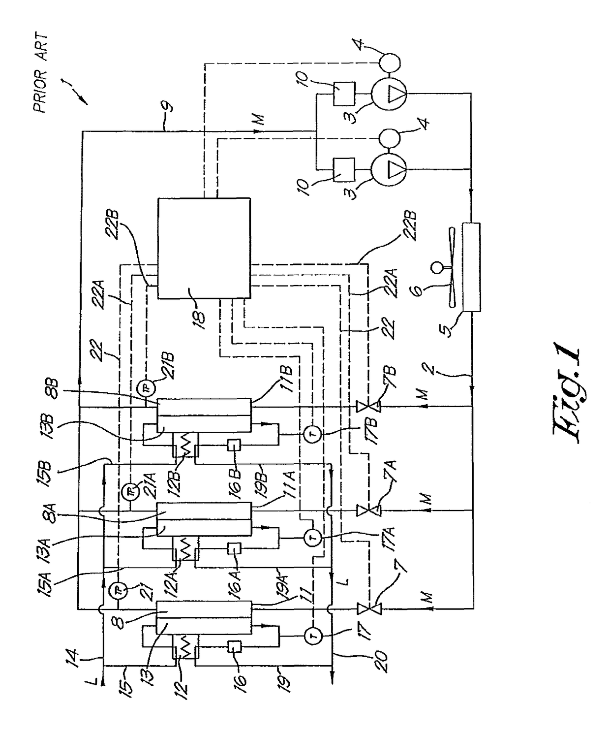
[0033]FIG. 1 shows a conventional cold drying installation 1 for cold drying gases that comprises a cooling circuit with a coolant in it, which can be driven around the circuit by one or more compressors connected in parallel by a drive by means of a motor 4 or similar.

[0034]The flow direction of the coolant in the cooling circuit 2 is indicated in the drawing by the arrows M.

[0035]Furthermore the cooling circuit successively comprises, in the flow direction of the coolant, a condenser 5 that connects to the outlet of the compressor(s) 3 and which is cooled, for example by means of a fan 6 or by means of water; controllable expansion valves 7, 7A, 7B, each with an evaporator 8, 8A, 8B connected to each of them. The evaporators 8, 8A, 8B are placed in parallel in the cooling circuit and their respective outputs are connected, via a joint collection pipe 9 and a liquid separator 10 for each compressor 3, to the input of the aforementioned compressor(s).

[0036]The sides of the respectiv...


PUM


Abstract

A cooling circuit is equipped with a coolant, a compressor, a condenser and evaporator expansion valve combinations, whereby the outlets of the evaporators are connected to a collection pipe connected to the compressor. The cooling circuit comprises a control unit connected to a temperature sensor and a pressure sensor affixed in the collection pipe and connected to the expansion valves for the control of them. The control unit is provided with an algorithm for controlling the expansion valves on the basis of the temperature sensor and pressure sensor to control the superheating in the collection pipe.

Description

BACKGROUND[0001]The present invention relates to a cooling circuit, a cold drying installation, and a method for controlling a cooling circuit.[0002]Water generally has to be removed from compressed gas, such as compressed air, before being supplied to a pneumatic network because the moisture in the gas can be harmful for the components and tools in the pneumatic network, as moisture can lead to corrosion or the accumulation of water in the tools that are not designed for this.[0003]A known technique for drying gas is known as cold drying, and this technique is based on the principle that by cooling the gas, moisture is evacuated from the gas that is saturated or partly saturated with water, because the moisture condenses and is removed as condensed water, after which the gas is heated up again so that it is no longer saturated and thus dryer.[0004]With cold drying a device is used that essentially consists of a closed cooling circuit that comprises a coolant that can be driven arou...

Claims


Application Information

Patent Timeline
Patent Type & Authority Patents(United States)
IPC IPC(8): F25B1/00F25B49/02F25B1/10F25B41/06F25B5/02B01D53/26
CPCF25B41/062F25B49/02B01D53/265F25B1/10F25B5/02F25B2600/21F25B2700/1933F25B2700/21151F25B2400/06F25B2600/0253B01D2257/80F25B41/34Y02B30/70
Inventor BALTUS, FRITS CORNELIS A.
Owner ATLAS COPCO AIRPOWER NV
Why Eureka
Try Eureka