Lock device

a technology of locking device and lock body, which is applied in the direction of non-mechanical control, building locks, construction, etc., can solve the problems of inefficiency of long-term systems, and achieve the effect of saving space and more spa

Active Publication Date: 2020-02-13
MONTAJES ELECTRONICSOS DORCAS
View PDF0 Cites 0 Cited by
  • Summary
  • Abstract
  • Description
  • Claims
  • Application Information

AI Technical Summary

Benefits of technology

[0045]This arrangement prevents the wear that occurs in the typical arrangement of a long bar and locking or interlocking lever since the preloaded opening function is separate from the locking function, said locking function being undamaged by wear. In addition, some embodiments of the present invention may be produced exclusively with linear movements, with no rotation. This also produces a considerable saving of space, which allows the available space to be used to install a larger actuator (preferably, a coil).
[0046]This arrangement is especially advantageous when the actuator is a preloaded opening actuator, that is, one in which, if an action is performed on the device which overcomes the force generated by the actuator, this allows the opening movement. Preferably, a device is pushed by the closure control (bolt or through-pin).
[0047]To save more space, the locking or retention device preferably moves from the locked or retained position to the unlocked position via a linear movement of an element that interacts with said part. Alternatively, pivoting sliding movements are also possible.

Problems solved by technology

In this situation, with the passage of time, the parts wear owing to the abrasion produced when preloaded opening occurs; this wear favours opening while compromising the locking function, and therefore it could indicate that in the long term the system is inefficient.
Since the system works using a tripping pin which is moved to the closed or open position by a very sensitive spring, and because the system is unidirectional, the mechanism functions better or worse depending on the position thereof in the installation.

Method used


Image

  • Lock device
  • Lock device
  • Lock device

Examples


Embodiment Construction

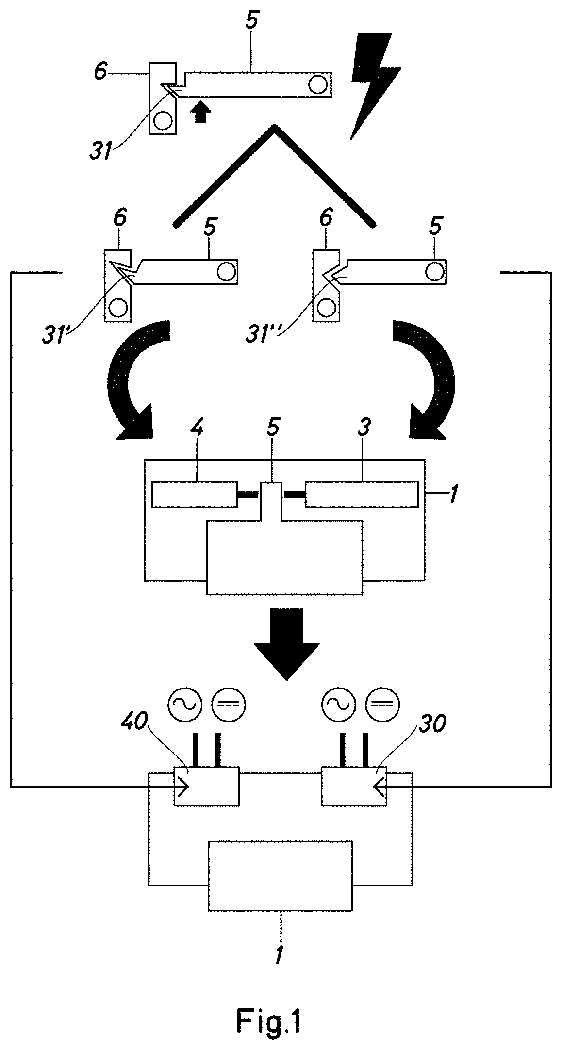
[0077]The upper portion of FIG. 1 shows a known type of central bar or part -5-, the retention force of which must be overcome by a bolt for opening to be possible. To prevent the device from opening, the position of the central part -5- is locked by means of an actuator -6-. In some embodiments of the opening device, the actuator -6- is known as a locking lever or short bar. Locking is achieved by means of a projection, end or part -31- of the actuator which is inserted in a corresponding housing receptacle in the central part -6-, being thus interlocked. Typically, this type of device has a single actuator, the function of which, when it receives an opening order, is to unmesh the central part -5- by retracting the bar of the actuator -6-.

[0078]Depending on the shape of the part -31- and of the corresponding housing receptacle, it may be easier or more difficult to force unlocking by an action transmitted through the central part itself (for example, an unauthorised opening attemp...


PUM


Abstract

Lock device (1) which incorporates a closure assembly (2) that can move between an open position and a closed position, a locking device to lock said closure assembly (2) in the closed position, a first actuator (3, 31) and a second actuator (4, 41), both the first actuator (3, 31) and the second actuator (4, 41) having a locked position, in which a locking or retention action is applied, and an unlocked position, both the first and the second actuators having respective control devices which allow orders to be given to change the position of each respective actuator, wherein the first actuator and the second actuator are arranged in such a way that unlocking the locking device requires that both control devices place their respective actuator in the unlocked position.

Description

CROSS-REFERENCE TO RELATED APPLICATION[0001]This application claims priority to European Patent Application No. 18382608.0 filed on Aug. 13, 2018, the disclosure of which including the specification, the drawings, and the claims is hereby incorporated by reference in its entirety.FIELD OF THE INVENTION[0002]The present invention relates to a lock device. More particularly, the present invention relates to a novel arrangement which has numerous advantages, including improving the operation of security locks or anti-panic locks, preferably in a small-size format, with regard to load situations, although this is only one of many advantages.[0003]The present invention may be applied to a wide range of lock devices, for example electric door openers, security doors, evacuation route doors and anti-panic doors, although the invention is not necessarily limited to said applications.BACKGROUND OF THE INVENTION[0004]Conventionally, door-opening devices have a single actuator (usually a coil)...

Claims


Application Information

Patent Timeline
Patent Type & Authority Applications(United States)
IPC IPC(8): E05B17/00E05B47/00E05B51/02
CPCE05B47/0001E05B17/0029E05B2015/0431E05B51/02E05B17/2007E05B15/00E05B47/0002E05B47/0047E05B2047/0013E05B2047/0073E05B2047/0076
Inventor IBAÑEZ ROIG, PABLOGONZALEZ SISTERNAS, JUAN
Owner MONTAJES ELECTRONICSOS DORCAS
Why Eureka
Try Eureka