Fuel deoxygenation system with non-metallic fuel plate assembly

a fuel plate and non-metallic technology, applied in liquid degasification, separation processes, lighting and heating apparatus, etc., can solve the problems of affecting the fuel line, inhibiting fuel delivery, and affecting the oxygen content of hydrocarbon jet fuel, so as to improve the oxygen diffusivity, cost-effective effect, and facilitate the sealing interface

Active Publication Date: 2009-08-04
RTX CORP
View PDF108 Cites 35 Cited by
  • Summary
  • Abstract
  • Description
  • Claims
  • Application Information

AI Technical Summary

Benefits of technology

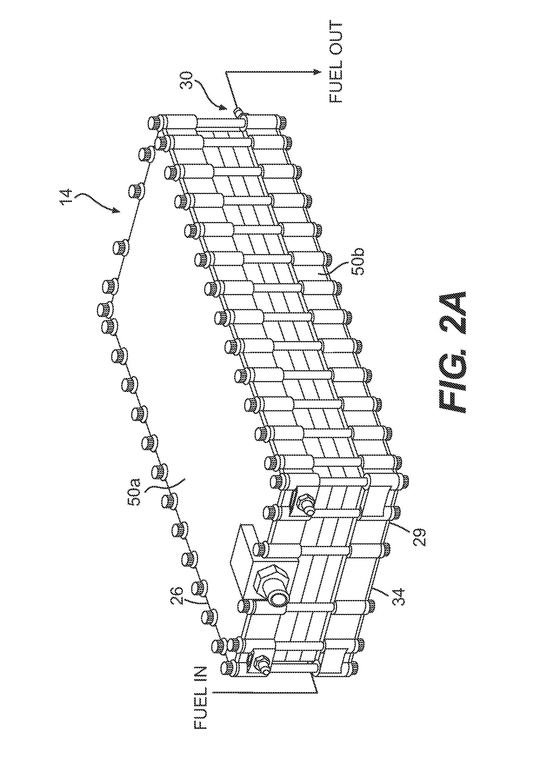
[0010]The fuel system for an energy conversion device according to the present invention includes a deoxygenator system that comprises a multiple of non-metallic fuel plates, gaskets, oxygen permeable membranes, porous substrate plates, epoxy film adhesive, liquid epoxy materials, and vacuum frame plates. The deoxygenator system is an on-line fuel stabilization unit (FSU) that deoxygenates fuel for use in aircraft thermal management applications. An important element of the FSU is the fuel plate. Intricate 3-dimension fuel channel structures such as laminar flow impingement elements within the fuel channel dramatically enhance oxygen diffusivity in the FSU. The fuel plates are manufactured from a relatively soft non-metallic material, such as various plastics or KAPTON®. Utilizing laser cutting with non-metallic materials permits cost-effective manufacture of relatively large area fuel plates with intricate 3-dimension fuel channel structures heretofore unavailable with metallic fuel plats.
[0011]The non-metallic fuel plates advantageously provide an effective sealing interface between the fuel plate and oxygen permeable membrane, since compression may be applied to the plates without damaging the relatively delicate oxygen permeable membrane. The non-metallic fuel plates permit manufacturing techniques for the intricate 3-dimensional fuel channel structures and correspondingly intricate sealing gaskets that seal and soften the contact between the fuel plates, the oxygen permeable membrane, and the non-metallic fuel plate as well as permit sealing within the fuel channel.

Problems solved by technology

The presence of dissolved oxygen in hydrocarbon jet fuels may be objectionable because the oxygen supports oxidation reactions that yield undesirable by-products.
When the fuel is heated between 300 and 850° F. the oxygen initiates free radical reactions of the fuel resulting in deposits commonly referred to as “coke” or “coking.” Coke may be detrimental to the fuel lines and may inhibit fuel delivery.
The formation of such deposits may impair the normal functioning of a fuel system, either with respect to an intended heat exchange function or the efficient injection of fuel.
Disadvantageously, the planar fuel plates are typically stainless steel which is relatively difficult, time-consuming, and expensive to machine while the oxygen permeable membrane is a relatively delicate, thin (˜2-5 microns) film which may lack mechanical integrity.
Contact between the metallic fuel plate and the oxygen permeable membrane may result in damage to the permeable membrane which necessitates careful manufacture and assembly to avoid leakage between the multitude of plates.
A failed seal between plates or a damaged permeable membrane may permit inter-stream leakage which may dramatically decrease the performance of the FSU.
Furthermore, to increase oxygen diffusivity and enhance fuel deoxygenator performance, the fuel plate includes a relatively intricate 3-dimension fuel channel structure which further complicates sealing and manufacture.
Although effective manufacturing techniques exist for the production of the relatively intricate 3-dimension fuel channel structure and the high-precision FSU sealing gaskets, these conventional techniques are exceedingly time consuming and expensive.

Method used


Image

  • Fuel deoxygenation system with non-metallic fuel plate assembly
  • Fuel deoxygenation system with non-metallic fuel plate assembly
  • Fuel deoxygenation system with non-metallic fuel plate assembly

Examples


Embodiment Construction

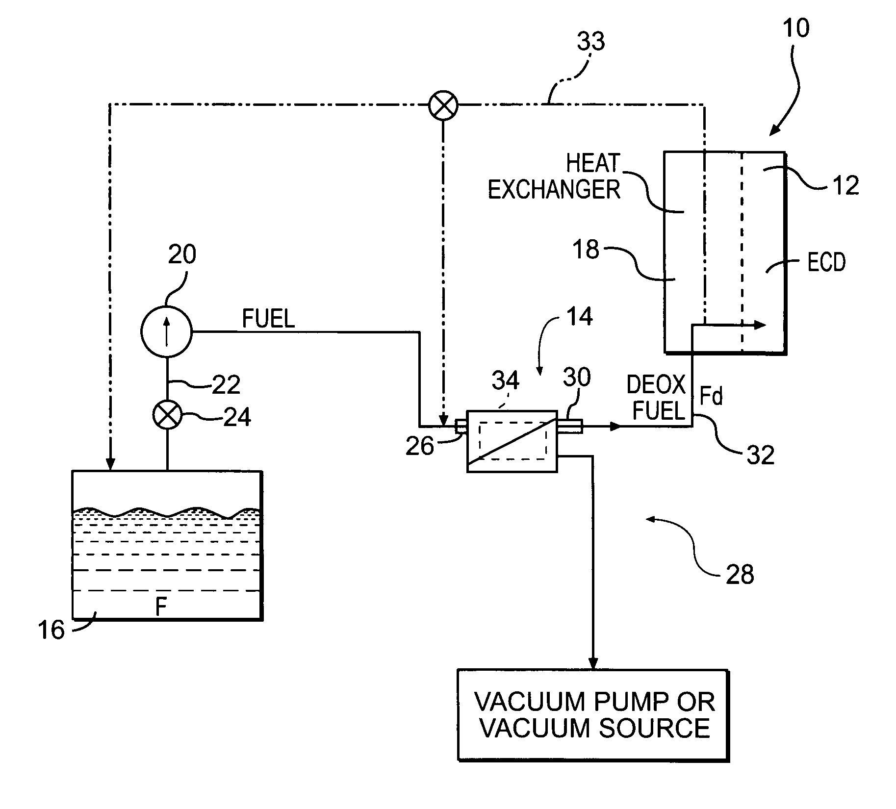
[0028]FIG. 1 illustrates a general schematic view of a fuel system 10 for an energy conversion device (ECD) 12. A deoxygenator system 14 receives liquid fuel F from a reservoir 16 such as a fuel tank. The fuel F is typically a liquid hydrocarbon such as jet fuel. The ECD 12 may exist in a variety of forms in which the liquid hydrocarbon, at some point prior to eventual use as a lubricant, or for processing, for combustion, or for some form of energy release, acquires sufficient heat to support autoxidation reactions and coking if dissolved oxygen is present to any significant extent in the liquid hydrocarbon.

[0029]One form of the ECD 12 is a gas turbine engine, and particularly such engines in aircraft. Typically, the fuel also serves as a coolant for one or more sub-systems in the aircraft and becomes heated as it is delivered to fuel injectors immediately prior to combustion.

[0030]A heat exchange section 18 represents a system through which the fuel passes in a heat exchange relat...


PUM

PropertyMeasurementUnit
oxygen permeableaaaaaaaaaa
concentrationaaaaaaaaaa
oxygen partial pressureaaaaaaaaaa

Abstract

A fuel system for an energy conversion device includes a multiple of non-metallic fuel plates, gaskets, oxygen permeable membranes, porous substrate plates, and vacuum frame plates. Intricate 3-dimension fuel channel structures such as laminar flow impingement elements within the fuel channel dramatically enhance oxygen diffusivity in the FSU. The fuel plates are manufactured from a relatively soft non-metallic material. The non-metallic fuel plates and gasket arrangement provide an effective sealing interface between the fuel plate and oxygen permeable membrane, since compression may be applied to the plates without damaging the relatively delicate oxygen permeable membrane.

Description

BACKGROUND OF THE INVENTION[0001]The present invention relates to stabilizing fuel by deoxygenation, and more particularly to a fuel plate assembly for a fuel stabilization unit.[0002]Fuel is often utilized in aircraft as a coolant for various aircraft systems. The presence of dissolved oxygen in hydrocarbon jet fuels may be objectionable because the oxygen supports oxidation reactions that yield undesirable by-products. Dissolution of air in jet fuel results in an approximately 70 ppm oxygen concentration. When the fuel is heated between 300 and 850° F. the oxygen initiates free radical reactions of the fuel resulting in deposits commonly referred to as “coke” or “coking.” Coke may be detrimental to the fuel lines and may inhibit fuel delivery. The formation of such deposits may impair the normal functioning of a fuel system, either with respect to an intended heat exchange function or the efficient injection of fuel.[0003]Various conventional fuel deoxygenation techniques are curr...

Claims


Application Information

Patent Timeline
Patent Type & Authority Patents(United States)
IPC IPC(8): B01D53/22
CPCB01D19/0031B01D19/0036B01D63/081B01D65/08B64D37/32B01D63/082Y02T50/44B01D2321/20Y10S55/05F23K2900/05082Y02T50/40B01D19/00B01D63/0822
Inventor COFFIN, CHARLES C.TILLMAN, THOMAS G.HUANG, HEWELCH, BRIAN M.
Owner RTX CORP
Why Eureka
Try Eureka