
Color filter substrate, liquid crystal display apparatus including color filter substrate, and method of manufacturing color filter substrate

a technology color filter substrate, which is applied in the direction of microlithography exposure apparatus, optics, instruments, etc., can solve the problems of image quality and display contrast degradation, and achieve the effect of improving the yield of liquid crystal display apparatus, excelling in display quality and display contras

Inactive Publication Date: 2009-08-04
SHARP KK
View PDF8 Cites 11 Cited by
  • Summary
  • Abstract
  • Description
  • Claims
  • Application Information

AI Technical Summary

Benefits of technology

[0011]The objective of the present invention is to provide (i) a color filter substrate that can improve the yield of a liquid crystal display apparatus by preventing an opposing electrode from short-circuiting with a pixel electrode and can provide a liquid crystal display apparatus that excels in display quality and display contrast, (ii) a liquid crystal display apparatus including the color filter substrate, and (iii) a method of manufacturing the color filter substrate.
[0016]The short circuit between the opposing electrode and the pixel electrode is prevented as above, so that the color filter substrate that can improve the yield of the liquid crystal display apparatus and can provide the liquid crystal display apparatus that excels in the display quality and the display contrast can be provided.
[0018]According to this arrangement, even if a conductive matter and the like exists in liquid crystal being in touch with the color filter substrate, it is possible to prevent the conductive matter from being in touch with the part of the opposing electrode on said at least one protruding structure section protruding from the substrate of the color filter substrate.
[0021]According the methods, the insulating layer is formed on the entire surface of the opposing electrode, so that it is possible to provide the method of manufacturing the color filter substrate that can prevent a foreign matter from being in touch with the part of the opposing electrode on said at least one protruding structure section protruding from the substrate of the color filter substrate.

Problems solved by technology

On this account, the alignment of the liquid crystal is spoiled and the leakage of light occurs, so that the image quality and display contrast deteriorate.

Method used


Image

  • Color filter substrate, liquid crystal display apparatus including color filter substrate, and method of manufacturing color filter substrate
  • Color filter substrate, liquid crystal display apparatus including color filter substrate, and method of manufacturing color filter substrate
  • Color filter substrate, liquid crystal display apparatus including color filter substrate, and method of manufacturing color filter substrate

Examples


embodiment 1

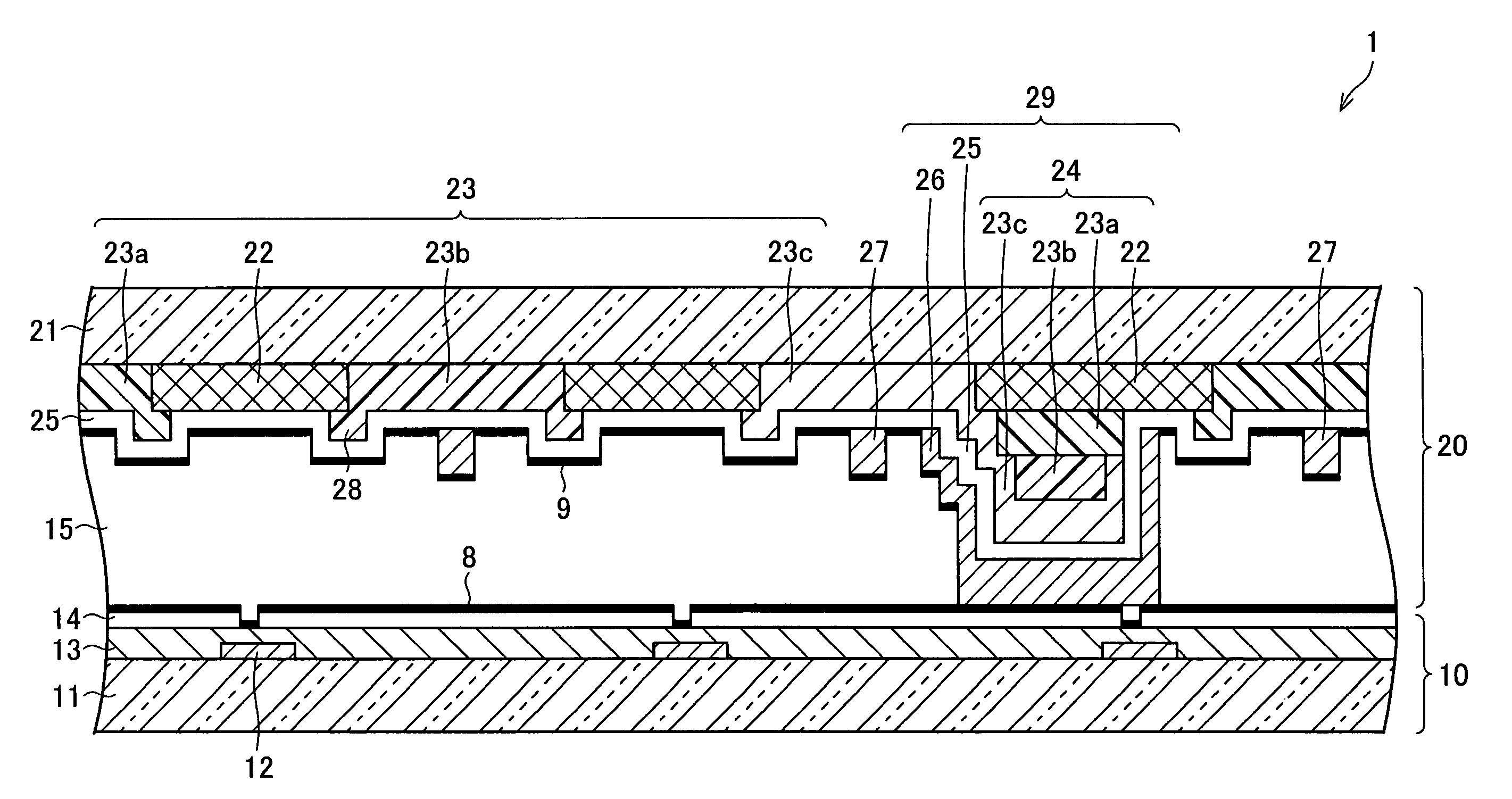
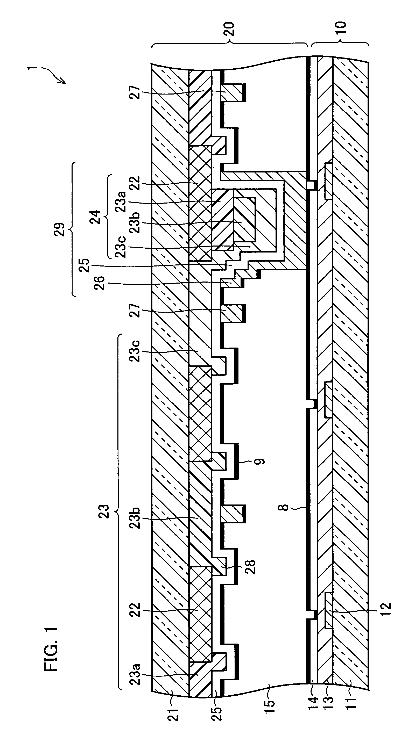
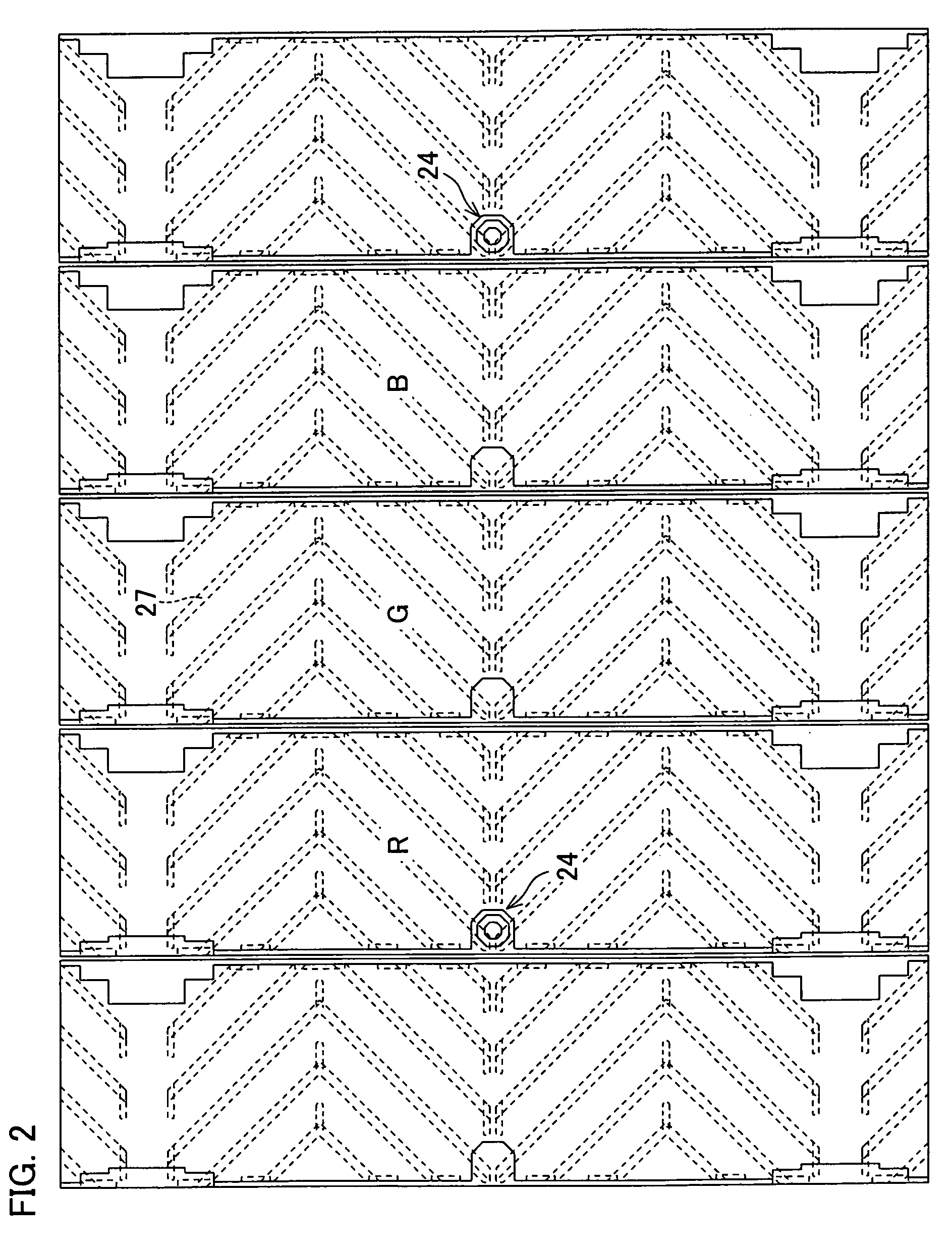
[0037]The following will describe an embodiment of the present invention in reference to FIGS. 1-6. FIG. 1 is a cross section of a liquid crystal display apparatus 1 of the present embodiment. FIG. 2 is a plan view of a color filter substrate of the present embodiment. Note that the liquid crystal display apparatus 1 of the present embodiment has a MVA (Multi-domain Vertical Alignment) structure. The structure of the liquid crystal display apparatus 1, however, is not limited to this MVA. Note that, the MVA structure is such an arrangement that liquid crystal molecules between a pair of substrate are vertically aligned when no voltage is applied, and one pixel is partitioned into more than one domain. That is, in the MVA structure, one pixel is partitioned into more than one domain in order to improve the viewing angle characteristics of a vertically-aligned liquid crystal display apparatus, and there are such methods of forming the domains as: cutting off, in a slit-shape, a pixel ...

embodiment 2

[0071]Another embodiment of the present invention will be described in reference to FIGS. 7-9. By the way, members having the same functions as those described in Embodiment 1 with figures are given the same numbers, so that the descriptions are omitted for the sake of convenience.

[0072]Being similar to the liquid crystal display apparatus illustrated in Embodiment 1, a liquid crystal display apparatus of the present embodiment is arranged such that an insulative resin film is provided on a stacked layer of a color filter substrate, and the stacked layer and the insulative resin film function as a spacer so that a cell gap is formed. The cell gap is formed with the spacer being elastically deformed to an appropriate degree, by suitably setting the size of the contact region between the insulative resin film on the color filter substrate and a pixel electrode of a TFT array substrate.

[0073]When the contact region between the insulative resin film and the pixel electrode is too large,...

embodiment 3

[0093]The following will discuss a further embodiment of the present invention in reference to FIGS. 10-12. By the way, members having the same functions as those described in Embodiment 1 with figures are given the same numbers, so that the descriptions are omitted for the sake of convenience.

[0094]In the stacked layer 24 as said at least one protruding structure section of Embodiments 1 and 2, not less than color layers (including the black matrix layer 22) are stacked. Present invention, however, is not limited to this, so that said at least one protruding structure section may include only two layers.

[0095]FIG. 10 shows a liquid crystal display apparatus 3 of the present embodiment. The liquid crystal display apparatus 3 does not include the black matrix layer 22 described in Embodiments 1 and 2, while includes a color filter substrate 40 that includes a stacked layer 44 in place of the stacked layer 24 and includes an insulative resin film (insulating layer) 46 in place of the ...


PUM

PropertyMeasurementUnit
thickaaaaaaaaaa
thickaaaaaaaaaa
thicknessaaaaaaaaaa

Abstract

A color filter substrate and a liquid crystal display apparatus include, on a substrate: a colorized layer including color layers; a stacked layer protruding in comparison with the colorized layer; an opposing electrode covering the colorized layer and the stacked layer; an alignment layer formed at least on a part of the opposing electrode covering the colorized layer; and an insulating layer stacked on an entire surface of another part of the opposing electrode covering the stacked layer. With this, the short circuit between the opposing electrode and a pixel electrode is prevented, so that a color filter substrate, a liquid crystal display apparatus including the color filter substrate, and a method of manufacturing the color substrate, those being able to improve the yield of the liquid crystal display apparatus, are provided.

Description

[0001]This Nonprovisional application claims priority under 35 U.S.C. § 119(a) on Patent Application No. 2003-432632 filed in Japan on Dec. 26, 2003 and Patent Application No. 2004-344645 filed in Japan on Nov. 29, 2004 the entire contents of which are hereby incorporated by reference.FIELD OF THE INVENTION[0002]The present invention relates to a color filter substrate, a liquid crystal display apparatus including the same, and a method of manufacturing the color filter substrate.BACKGROUND OF THE INVENTION[0003]A liquid crystal display apparatus is typically arranged in such a manner that liquid crystal is enclosed between a pair of substrate opposing to each other. That is, in a liquid crystal display apparatus shown in FIG. 13, liquid crystal 75 is enclosed between a TFT (Thin Film Transistor) array substrate 70 and a color filter substrate 80. The TFT array substrate 70 is arranged such that a TFT circuit layer 72 including TFT elements and the like, an insulative layer 73, and ...

Claims


Application Information

Patent Timeline
Patent Type & Authority Patents(United States)
IPC IPC(8): G02F1/1335G02F1/1339G02B5/20G02F1/1333G02F1/136G03F7/20
CPCG02F1/13394G02F1/133514G02F1/133512G02F1/1335
Inventor YAGI, TOSHIFUMITSUBATA, TOSHIHIDETOKUDA, TSUYOSHI
Owner SHARP KK
Learn More