Surgical operation device

a surgical and operation device technology, applied in the direction of electrical programme control, surgical forceps, program control, etc., can solve the problem of no master arm or operation device that intuitively propagates

Inactive Publication Date: 2009-08-11
JAPAN SCI & TECH CORP
View PDF14 Cites 16 Cited by
  • Summary
  • Abstract
  • Description
  • Claims
  • Application Information

AI Technical Summary

Benefits of technology

[0015]Therefore, when it is desired to make the holder move subtly, the operator can make the holder of the slave move as the finger of the operator moves, without combining various rotations and movements of the arm of the slave.
[0016]This enables microsurgery to be easily performed by using the surgical operation device.
[0019]In the above structure, because the second sensor to the fourth sensor are torque sensors, it is possible to input operator-intended-movement by applying subtle forces. In addition, because the movement ratio is changeable through the calculation section, the movement can be transmitted as enlarged movement. Moreover, a weight of a glove can be reduced, as an additional effect. Therefore, the operator would not be required to make large movements of his / her hand in order to move the holder. In other words, small movements of the hand of the operator are sufficient to transmit the movement. Accordingly, in addition to the effect in the above structure, because the movement ratio can be changed by calculation, the surgery can be more easily performed by using the surgical operation device. As described above, the movement ratio between the master and the slave is variable, and the movement ratio may vary in different axes.

Problems solved by technology

However, there is no master arm or operation device that intuitively propagates the movement of a hand / wrist / carpal joint or a finger that operates the surgical appliance to a slave arm.

Method used


Image

  • Surgical operation device
  • Surgical operation device
  • Surgical operation device

Examples


Embodiment Construction

[0024]The following describes an embodiment of the present invention.

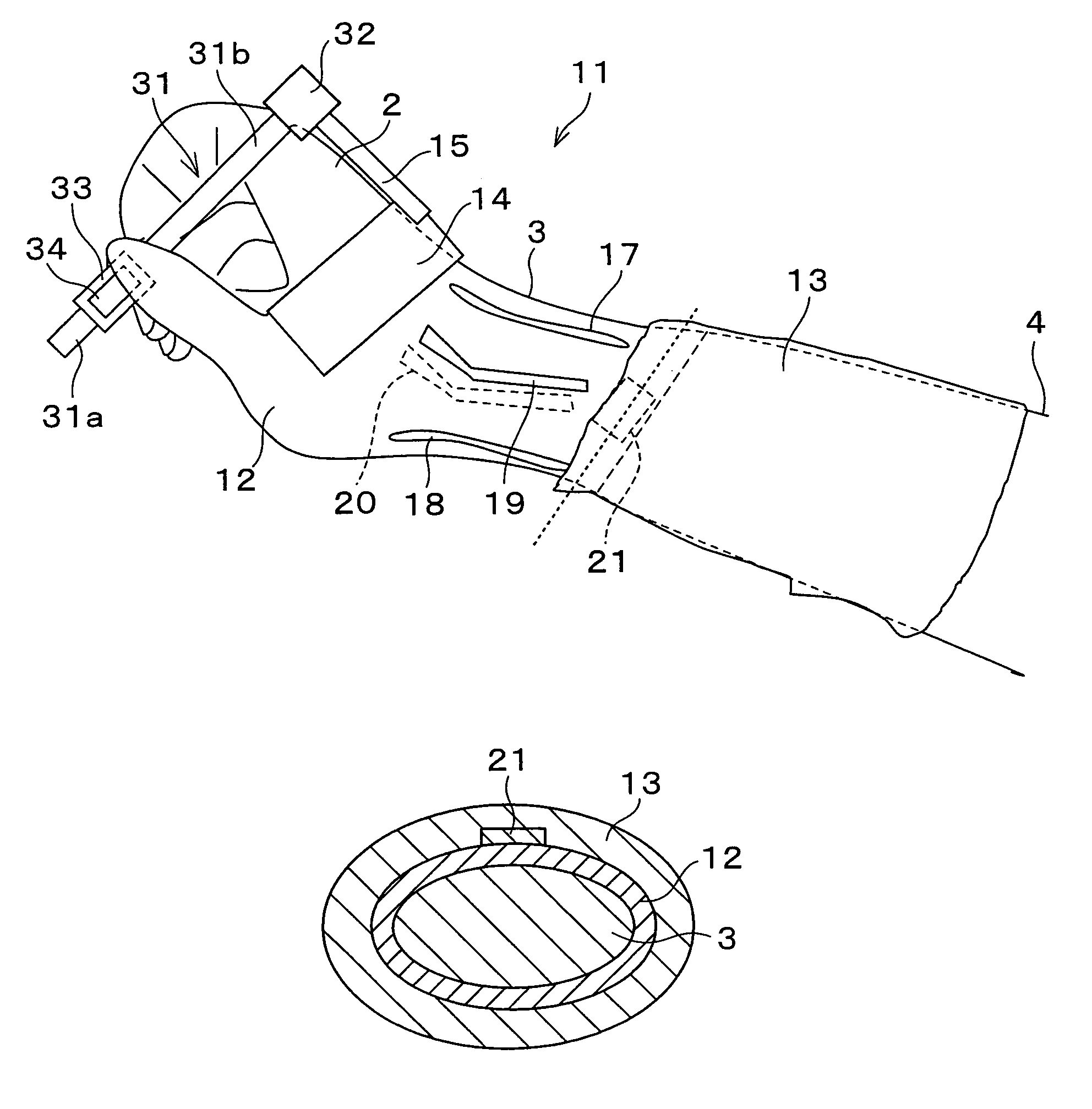
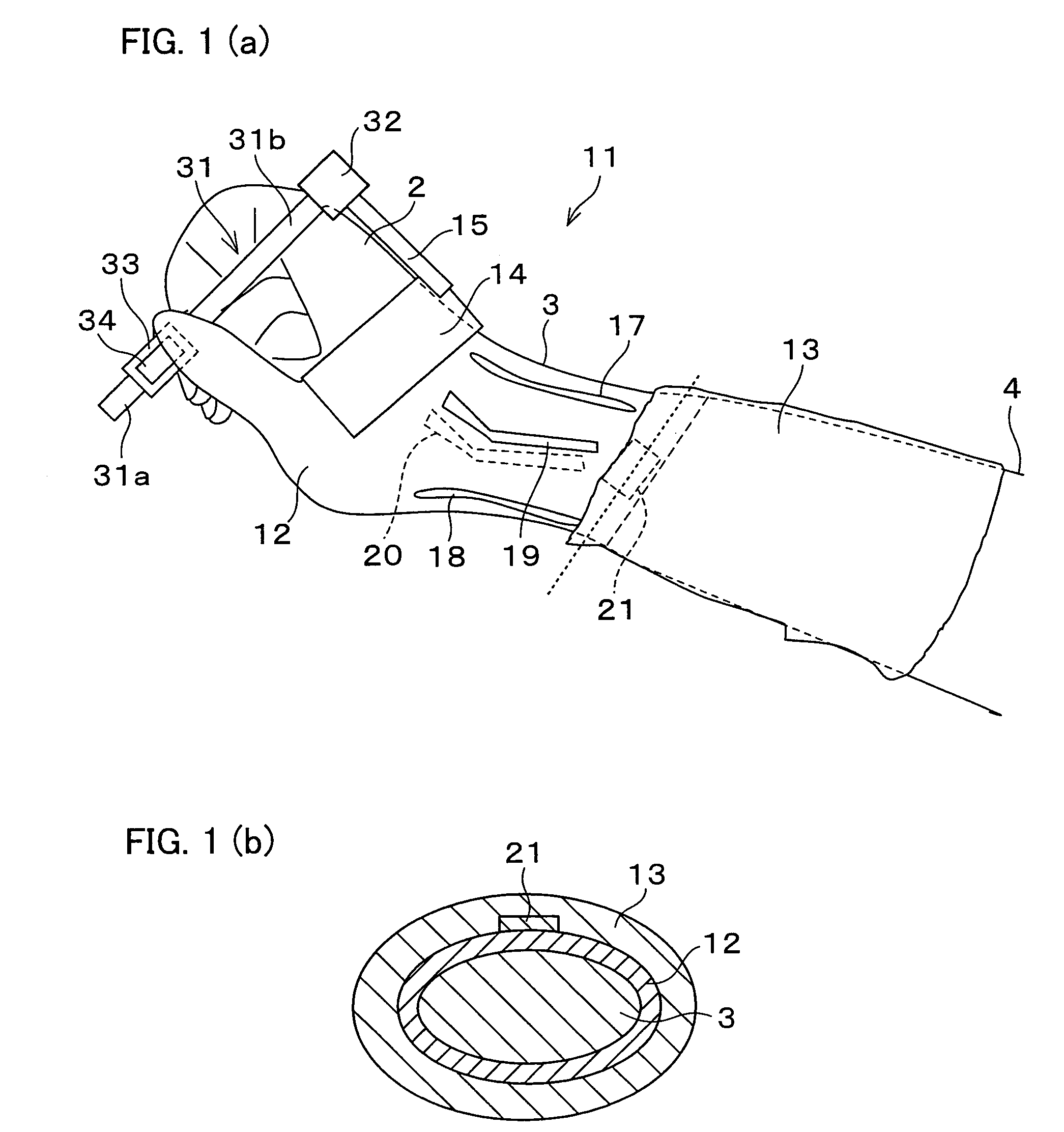
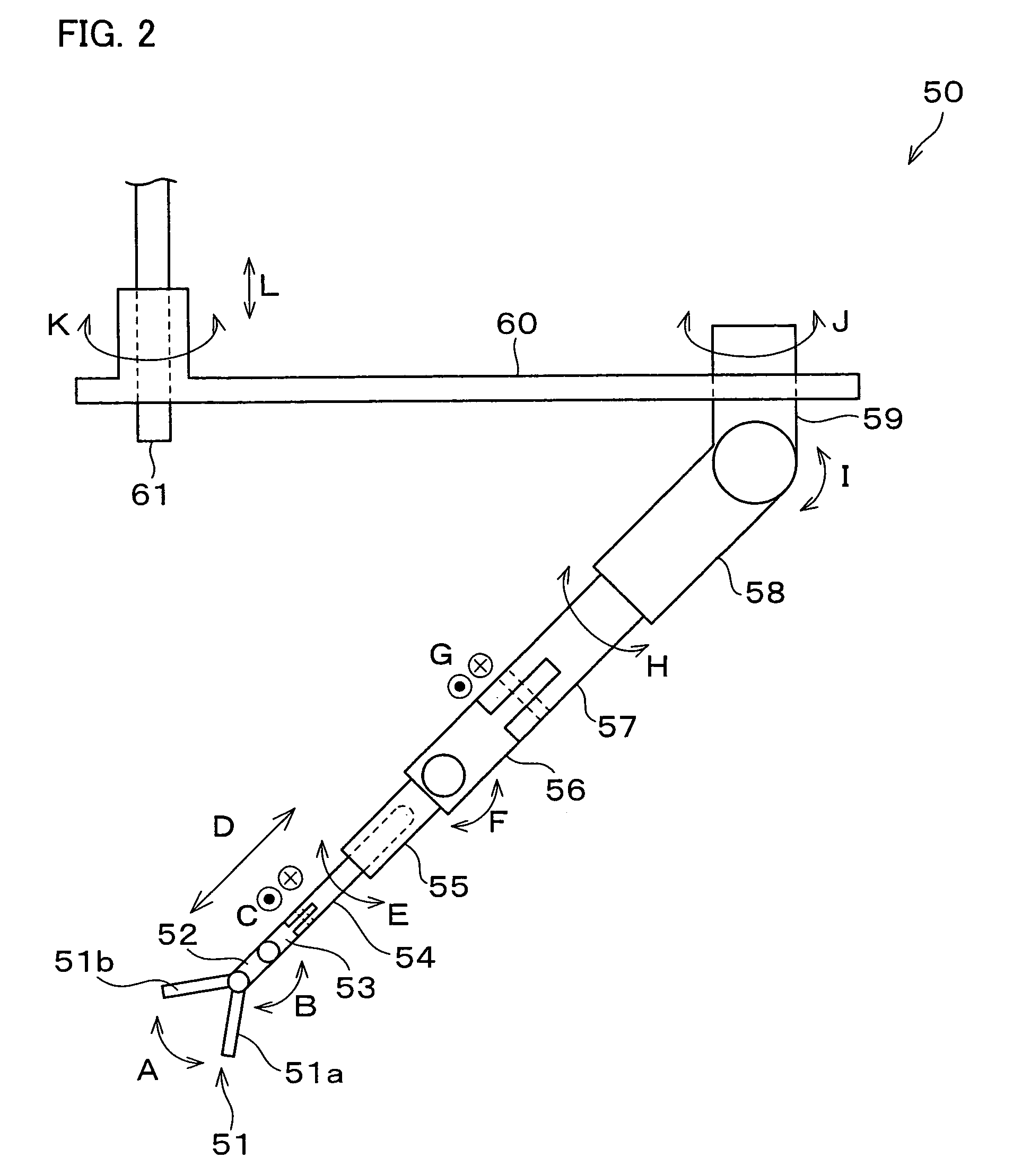
[0025]A surgical operation device in connection with the embodiment performs surgical operations, mainly separation or suture of micro tissue such as a vessel, a nerve, or lymph duct, and includes a micro-soft-tissue-suture-assisting manipulator as a slave.

[0026]In order to suture a microvessel (especially one having a diameter of 1 mm or less), it is necessary to grip a needle-holder with a right hand unit and to precisely insert a needle point of a 10-0 or 11-0 suture needle (10-0 and 11-0 are part numbers of the suture needle), in which the tip of the suture needle is approximately between 5 μm and 70 μm, into the vessel wall at a right angle. In order to do so, it is necessary to use an appliance acting as a needle-holder, the end of which is capable of sensitive movement.

[0027]Generally, in a micro suture operation, the right hand rotates a hand joint to adjust the tip of the needle in such a way that the tip ...


PUM


Abstract

In order to rotate and move an arm of a slave which supports a needle-holder, the rotation and movement of a pen-shaped operating section (31) caused by the fingers of the operator's hand are directly transmitted as the rotation and movement of the needle-holder, as sensors for detecting the rotation and movement of the operating section, an X-axis torque sensor, Y-axis torque sensor, Z-axis torque sensor, and a rotation detecting potentiometer (33) are installed thereon. As a result, the rotation and movement of the pen-shaped operating section (31) caused by the fingers of the operator's hand are transmitted as the rotation and movement of the needle-holder in optimum proportions through a computing section. Therefore, when the needle-holder is to be finely moved, a subtle motion of the fingers of the hand can be satisfactorily transmitted. Thereby, it is possible to provide a surgical operation device capable of doing minute surgical operations with ease.

Description

TECHNICAL FIELD[0001]The present invention relates to a surgical operation device using a master and a slave for performing a micro surgical operation.BACKGROUND ART[0002]Various surgical operation devices using a master and a slave for performing an operation have been developed; examples thereof can be found in the following references:[0003]Japanese Unexamined Patent Publication No. 2001-137257 (published on May 22, 2001),[0004]Japanese Unexamined Patent Publication No. 7-136173 (published on May 30, 1995),[0005]Japanese Unexamined Patent Publication No. 7-194609 (published on Aug. 1, 1995),[0006]Japanese Unexamined Patent Publication No. 8-117238 (published on May 14, 1996),[0007]Japanese Unexamined Patent Publication No. 7-184929 (published on Jul. 25, 1995),[0008]Computer-guided Microsurgery: Surgical Evaluation of a Telerobotic Arm (Microsurgery Vol. 21, No. 1 (2001), pp. 22-29).[0009]Japanese Unexamined Patent Publication No. 2001-137257 discloses a remote manipulation devic...

Claims


Application Information

Patent Timeline
Patent Type & Authority Patents(United States)
IPC IPC(8): G05B19/18A61B1/00A61B17/00A61B17/06A61B17/42A61B19/00A61D1/06B25J17/00G06F19/00B25J3/00A61B17/04A61B17/28B25J13/08
CPCA61B19/2203A61B19/201A61B2019/2223Y10T74/20305A61B2019/2273A61B2019/464Y10T74/20335A61B2019/223A61B34/30A61B34/35A61B34/37A61B90/11A61B2034/741A61B2090/064
Inventor GOTANI, HIROYUKI
Owner JAPAN SCI & TECH CORP
Why Eureka
Try Eureka