System and method for IM3 reduction and cancellation in amplifiers

a technology of im3 reduction and cancellation, applied in amplifiers, amplifiers with semiconductor devices/discharge tubes, amplifier modifications to reduce noise influence, etc., can solve the problems of difficult elimination or even reduction, less efficient operation, and degradation in the other direction, so as to maximize the cancellation minimize electrical parasitics, and maximize the effect of at least one distortion componen

Inactive Publication Date: 2009-08-11
MICROSEMI CORP
View PDF6 Cites 4 Cited by
  • Summary
  • Abstract
  • Description
  • Claims
  • Application Information

AI Technical Summary

Benefits of technology

[0013]In another embodiment, the first biasing circuit first impedance and first biasing level differs from the second biasing circuit second impedance and second biasing level. In other embodiments, the impedance of the first and second biasing circuits and a biasing level of the first and second branches are different, and the impedance of the third and fourth biasing circuits and a biasing level of the third and fourth branches is different and are chosen so as to maximize the cancellation of the at least one distortion component at the output of at least one of the first stage and the second stage of the discrete amplifier.
[0014]In yet other embodiments, the first, the second, the third and the fourth branches are formed on a single integrated circuit chip and the first biasing circuit, the second biasing circuit, the third biasing circuit and the fourth biasing circuit are physically located on the same single integrated circuit chip to minimize electrical parasitics so as to maximize the cancellation of the at least one distortion component. Other embodiments further comprise a sensing circuit that senses the input power to the discrete amplifier and causes at least one of the first, the second, the third and the fourth biasing circuits to adjust the operating mode of its respective branch by adjusting at least one of the bias circuit current and impedance so as to maximize the cancellation of the at least one distortion component.

Problems solved by technology

In conventional power amplifier designs, improvement in one area typically causes degradation in the other.
Intermodulation distortion (IMD) occurs as a result of nonlinearities in the amplifier transfer function resulting in mixing products being generated at the sum and difference frequencies of the input signals.
Being located so close to the carrier signal, IMD3 is very difficult to eliminate or even reduce and is often the limiting factor in the linearity of the RF / microwave amplifier.
A drawback to this method is that when the device is operated at a lower power level it is operating less efficiently than it does at higher power levels.

Method used


Image

  • System and method for IM3 reduction and cancellation in amplifiers
  • System and method for IM3 reduction and cancellation in amplifiers
  • System and method for IM3 reduction and cancellation in amplifiers

Examples


Embodiment Construction

[0032]Reference will now be made in detail to presently preferred embodiments of the invention, one or more examples of which are illustrated in the accompanying drawings. Each example is provided by way of explanation of the invention, not limitation of the invention. In fact, it will be apparent to those skilled in the art that modifications and variations can be made in the present invention without departing from the scope and spirit thereof. For instance, features illustrated or described as part of one embodiment may be used on another embodiment to yield a still further embodiment. Thus, it is intended that the present invention covers such modifications and variations as come within the scope of the appended claims and their equivalents.

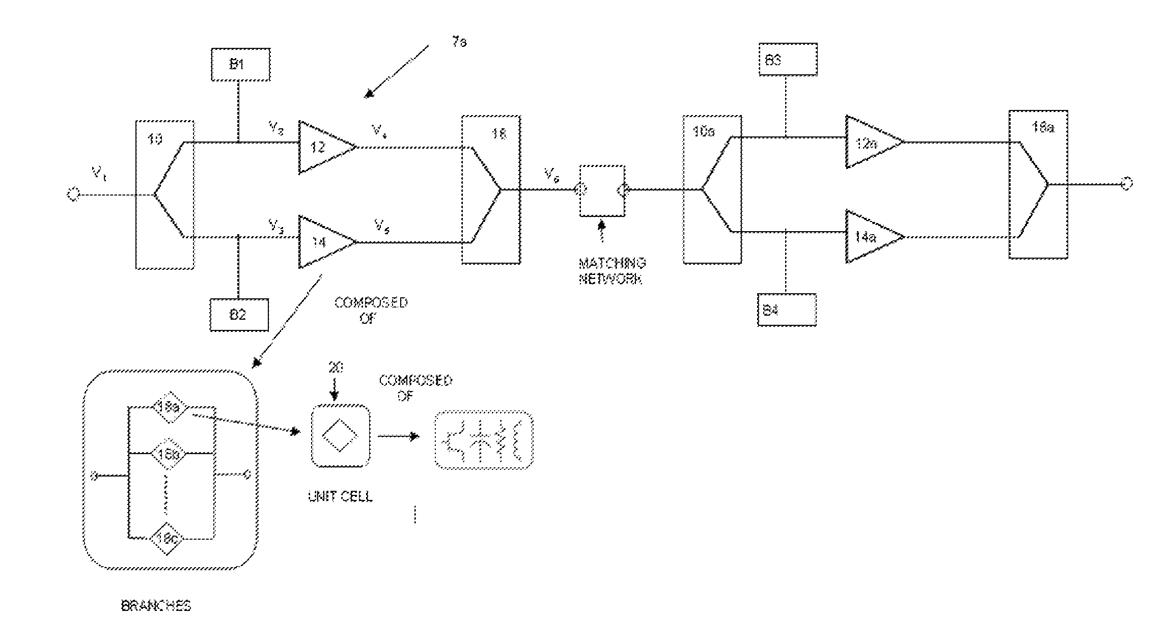
[0033]The present invention seeks to reduce or significantly cancel the IM3 levels in power amplifiers at one or both of the component level and the sub-component level of the amplifier. In a first embodiment shown in FIG. 3, a component leve...


PUM


Abstract

Sets of power amplifier branches (which comprise an RF / microwave amplifier stage) are power combined within each stage and each set of power amplifier branches are biased in different classes of operation by bias circuits possessing different impedance characteristics such that the fundamental frequency components present at the output are in-phase with one another and the IMD3 components are anti-phase over a broad range of power levels. The RF input signal is provided by the output of the previous stage of the RF / microwave amplifier. The output of each stage is formed by power combining sets of these power amplifier branches, each of which are separately biased, so the fundamental components are additive resulting in the maximum possible output power and the IM3 components cancel partially or completely. IM3 reduction or cancellation can be achieved over a large range of output powers with the use of a feed forward control loop monitoring the input power and appropriately adjusting the bias currents and impedance characteristics of the bias circuits feeding the individual power amplifier branches in each stage of the RF / microwave amplifier.

Description

CLAIM OF PRIORITY[0001]This application claims priority to U.S. Provisional Application No. 60 / 771,924, filed on Feb. 9, 2006 and U.S. Provisional Application No. 60 / 850,146, filed on Oct. 6, 2006, the entire disclosures of which are incorporated by reference herein.FIELD OF THE INVENTION[0002]This invention generally relates to radio frequency / microwave amplifiers for communication devices, and in particular, to a system and method for automatically reducing third order intermodulation product levels to reduce signal distortion and maintain high data rates for communication systems over a wide range of frequencies.BACKGROUND OF THE INVENTION[0003]Amplifiers are used in all cell phones to amplify a modulated signal from a transceiver prior to passing the signal through the front end of the cell phone, which typically consists of passive components and a switch into an antenna where the signal is transmitted to a base station. FIG. 1 illustrates a high level topography of the circuit...

Claims


Application Information

Patent Timeline
Patent Type & Authority Patents(United States)
IPC IPC(8): H03F1/26
CPCH03F1/0266H03F1/32H03F1/3223H03F3/211H03F2203/21118H03F2200/198H03F2200/432H03F2200/465
Inventor KRISHNAMURTHY, VIKRAM BIDAREKHANIJOUN, TANVEER KAURHERSHBERGER, KYLE MARKREED, JEREMY THOMASPACE, PAUL ERIK
Owner MICROSEMI CORP
Why Eureka
Try Eureka