Distortion detection for a power amplifier

Inactive Publication Date: 2005-09-27
ANDREW LLC
View PDF7 Cites 1 Cited by
  • Summary
  • Abstract
  • Description
  • Claims
  • Application Information

AI Technical Summary

Benefits of technology

[0009]In the preferred embodiment, the frequency ranges are substantially the same, and the isolating step may involve frequency converting the input and output signal to produce the first and second signals. Preferably, the frequency conversion is frequency down-conversion which means that the resulting signals are of lower frequency and therefore provide less demands on the devices used to handle them. Advantageously, the same signal can be used to frequency down-convert both the input and output signals.
[0010]The isolating step may be performed at a series of different frequency ranges. The series may be such that at least two adjacent ranges overlap or abut one another. Alternatively, it can be arranged that at least two of the ranges are discontinuous, so that complete frequency coverage is not provided. In one embodiment, the isolating step traverses the series of ranges in a sequence which is not in frequency order. This may help to avoid interactions between the temporal characteristics of the input signal and the isolating step sequence.
[0014]The comparison step may involve transforming the residual signal to the frequency domain for further analysis. In this way, the spectrum of the residual distortion can be analysed. Preferably, the first signal is also transformed to the frequency domain (e.g. by FFT), thus allowing comparisons to be made between the two spectra. For example, the spectrum of the first signal may be used to identify any remaining wanted signal components which have not been removed from the residual distortion signal or to provide a reference against which the magnitude of components in the residual distortion spectrum can be measured.
[0015]In a particularly preferred embodiment, the inventive method and apparatus for detecting distortion is used to control a distortion reduction mechanism operating on a distorting signal handling means. In this way, the distortion reduction mechanism may be adapted to maximise the cancellation of the distortion created by the signal handling means. For example, the distortion reduction mechanism could be a predistortion lineariser or a feed-forward lineariser.

Problems solved by technology

The use of pilot signals for distortion detection has the disadvantage that a pilot signal must be generated, detected and then removed from the output signal afterwards.
Thus, the use of pilot signals increases system complexity and adds the risk that spurious noise or continuous wave (CW) emissions introduced by the pilot signal detection system will remain as unwanted residues in the amplifier output.

Method used


Image

  • Distortion detection for a power amplifier
  • Distortion detection for a power amplifier
  • Distortion detection for a power amplifier

Examples


Embodiment Construction

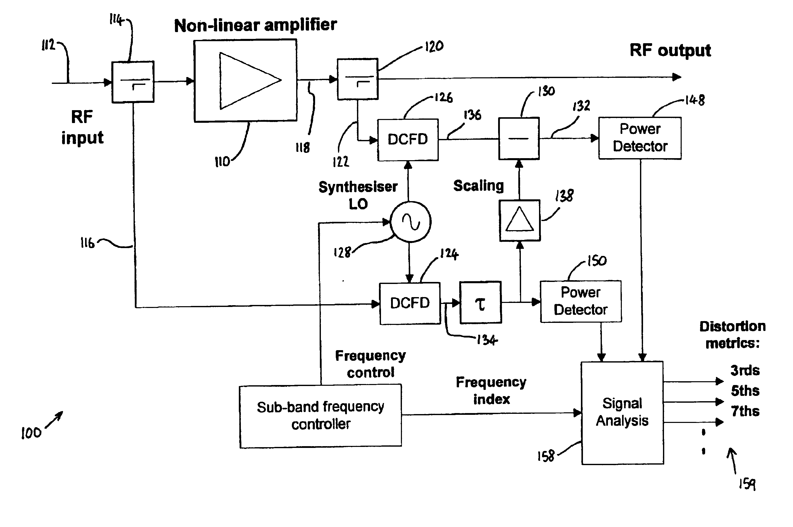
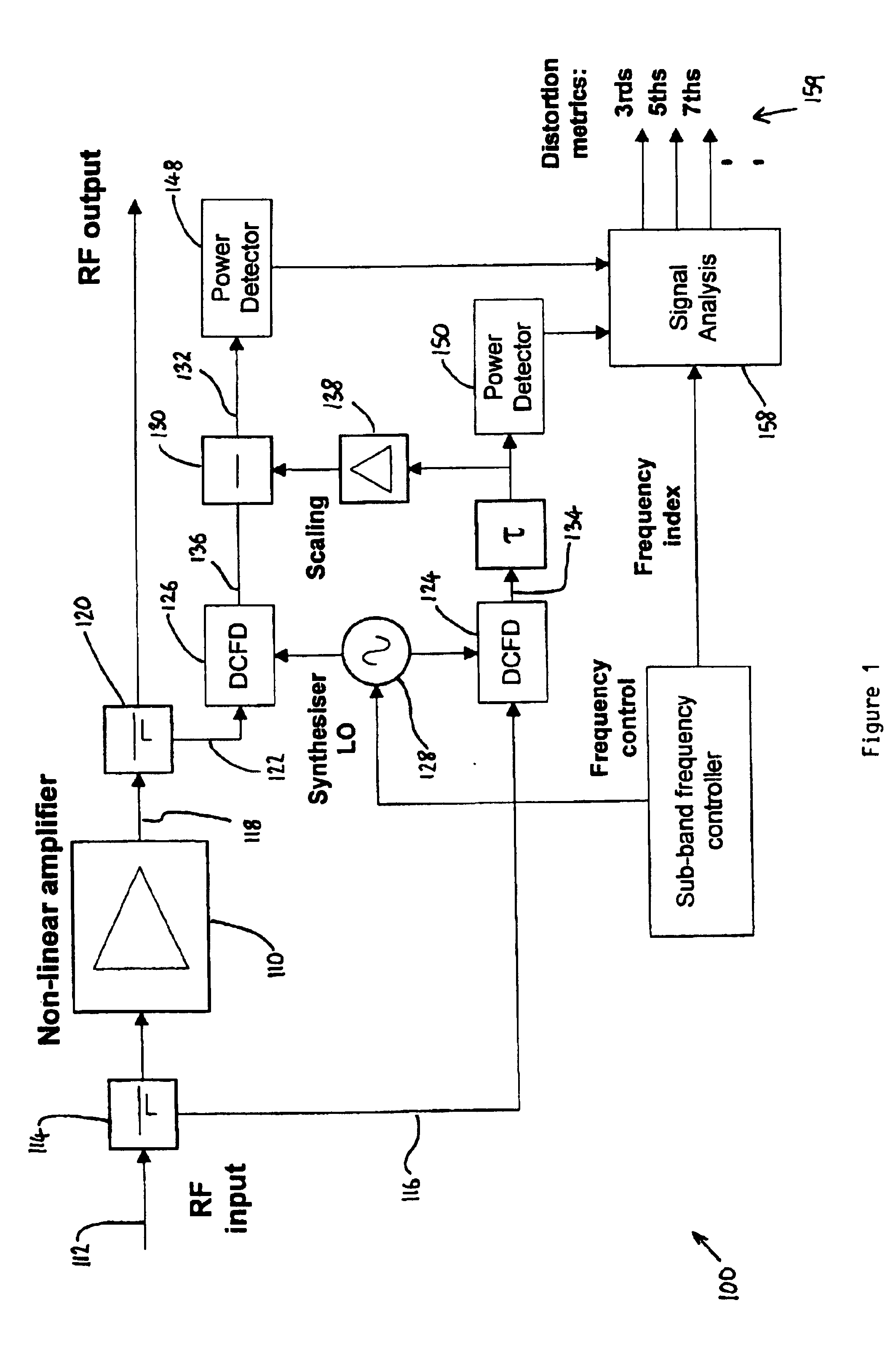
[0018]Distortion detection scheme 100 in FIG. 1 operates on non-linear amplifier 110. Amplifier 110 is a wide band radio frequency power amplifier having a non-linear characteristic such that it imposes intermodulation distortion upon signals passing through it. The distortion detection scheme 100 provides signals indicative of this distortion which can be used by an appropriate distortion reduction mechanism (not shown), for example, a predistorter operating on the input 112 to amplifier 110, subsequent to coupler 114.

[0019]The input signal 112 is sampled at coupler 114 along path 116. The output 118 of the amplifier 110 is sampled at coupler 120 along path 122. The signals on paths 116 and 122 are frequency down-converted and filtered by Down Conversion, Filtering and Digitisation (DCFD) units 124 and 126 respectively. The downconversion performed by units 124 and 126 is performed by mixing the incoming signal with a local oscillator (LO) signal from frequency controlled synthesis...


PUM


Abstract

The input and output of amplifier (110) are sampled and downconverted in frequency and filtered at (124 and 126) to produce sub-band signals. The input signal sub-band (134) is then subtracted from the output signal sub-band (136) at (130) to produce a residual signal (132) containing any distortion present in the sub-band selected by the downconversion oscillator (128). Signal analyser (158) compares the input and output signal energy to deduce the amount of distortion in the output signal, to provide signals for controlling a distortion reduction mechanism such as a predistorter operating on amplifier (110). Alternatively, the input signal sub-band (134) and the output signal sub-band (136) are Fourier transformed (210 and 212) to produce spectrums which can be analysed to determine the presence of distortion in the output of amplifier (110).

Description

BACKGROUND OF THE INVENTION[0001]1. Field of the Invention[0002]This invention relates to methods and apparatus for detecting distortion in an output signal which a signal handling means (such as an amplifier) produces in response to an input signal.[0003]2. Description of the Related Art[0004]It is known to use distortion reduction mechanisms on amplifiers in an attempt to linearise the amplifier's response. It is often desirable to monitor residual distortion in the output of the amplifier, and to use this signal to adapt the distortion reduction mechanism to maximise the cancellation of the distortion. It is known to use a pilot signal to detect residual distortion. The pilot signal is added to the input signal and detected in the output signal so that any distortion it experiences can be assessed. The use of pilot signals for distortion detection has the disadvantage that a pilot signal must be generated, detected and then removed from the output signal afterwards. Thus, the use...

Claims


Application Information

Patent Timeline
IPC IPC(8): H03F1/32
CPCH03F1/3247H03F1/3258
Inventor RING, STEVEN R.
Owner ANDREW LLC
Why Eureka
Try Eureka