Crosstalk cancellation using sliding filters

a technology of sliding filters and crosstalk, applied in the field of communication systems, can solve the problems of affecting the reception of the desired signal being transmitted on the victim channel, introducing interference into the other channels, and affecting the processing and decoding of the received signals transmitted over channels, etc., to achieve the effect of maximizing the crosstalk cancellation associated

Active Publication Date: 2009-03-26
MARVELL ASIA PTE LTD
View PDF63 Cites 10 Cited by
  • Summary
  • Abstract
  • Description
  • Claims
  • Application Information

AI Technical Summary

Benefits of technology

[0015]In one variation, the first signal is filtered with a FFE filter and the second signal is filtered with a second FFE signal. Using this method, the step of combining may be performed by one or more junctions configured to subtract a cancellation signal from a delayed signal. In addition, the multichannel communication system may comprise four channels and each channel may receive a cancellation signal from each of the other channels. In one embodiment the step of delaying the first filtered signal and delaying the first delayed signal or the first cancellation signal time aligns the first cancellation signal with the second delayed signal.
[0016]Also disclosed is a system for crosstalk cancellation in a multichannel communication system such that the system for crosstalk cancellation maximizes the crosstalk cancellation associated with each channel. In this embodiment, the system comprises one or more in-line filters configured to filter a received signal to create a filtered in-line signal and one or more delays configured to time delay the filtered signal to create a delayed in-line signal. This embodiment also comprises one or more cross-connect systems comprising one or more filters, one or more outputs configured to carry a cancellation signal to a junction associated with another channel, such that the cross-connect system is configured to process the delayed in-line signal and generate a cancellation signal. In this embodiment, one or more junctions are configured receive one or more cancellation signals from one or more other channels.
[0017]In one embodiment, the cross-connect system further comprises one or more cross-connect delays. The in-line filters may comprise a FFE type filter. In one embodiment, at least one of the one or more cross-connect delays is set to zero delay. In addition, the in-line delay may be configured to have at least as much delay as required for the cancellation of any one of the one or more cross-connect delays to be maximized.
[0018]Also disclosed herein is a method for training a crosstalk cancellation system, for each channel. In one embodiment, the method comprises providing a crosstalk cancellation system comprising one or more in-line filters, one or more in-line delays, one or more cross-connect filters, one or more cross-connect delays and a memory. Using this system, setting one or more in-line delays and one or more cross-connect delays to zero delay and training the one or more in-line filters. Also training the one or more cross-connect filters to generate cross-connect filter coefficients and then store the cross-connect filter coefficients. Then retraining the one or more in-line filters and storing of the resulting in-line filter coefficients with the cross-connect filter coefficient as a filter coefficient set occurs. Thereafter, the method establishes offset in one or more in-line delays and retraining the one or more in-line filters and the one or more cross-talk filters with offset to establish new coefficient set. These are stored and then the method establishes additional offsets. For each additional offset retraining occurs on the one or more in-line filters and the one or more cross-talk filters to create a filter coefficient set associated with each offset, which is stored with the additional filter coefficients sets associated with each offset. The method then analyzes the filter coefficient sets to determine the offset which maximized cancellation for each of the cross-talk paths. The method then identifies the maximum cancellation offset of these cancellation offsets calculated for each cancellation filter. The method thereafter establishes one or more in-line filters with a coefficient set which corresponds to maximum cancellation offset and also establishes one or more in-line delays with offset which corresponds to the maximum cancellation offset found in the last step. The method also establishes one or more cross-connect filters with coefficient set which corresponds to maximum cancellation offset, and establishes one or more cross-connect delays with offset which corresponds to maximum cancellation offset.
[0019]This method may further comprise analyzing the offset for the one or more cross-connect delays to determine a cross-connect delay with a maximum delay and establishing the one or more in-line delays to have the same amount of delay as the cross-connect delay with the maximum delay. Then the method resets the cross-connect delay which had the maximum delay amount to zero and also adjusts the remaining cross-connect delays to maintain the same amount of delay at the output by taking into account the newly established in-line delay. The method establishes one or more cross-connect filters with coefficient sets that correspond to the maximum cancellation offset for each cross-connect filter. The one or more in-line filters may comprise one or more in-line FFE type filters. It is contemplated that this method may be performed in a four channel communication system. It is contemplated that during training one or more coefficient set may be stored in memory.

Problems solved by technology

In all of these instances, coupling between channels of a multi-channel communication system may occur, thereby introducing interference into the other channels.
Thus, signals on each of the adjacent channels, i.e., the disturber signals on the disturber channels, often couple into the victim channel 108A and thereby interfere with reception of the desired signal being transmitted on the victim channel.
Hence, the processing and decoding of the received signals transmitted over channels 108A-108D is made more difficult by the coupling that occurs between channels.
While attempts have been made to overcome the effects of coupling, none of these attempts adequately reduces the presence or effects of crosstalk.
The Agazzi reference does not, however, eliminate sufficient coupling to overcome all the drawbacks of the prior art, and hence, even when adopting the teachings of the Agazzi reference, coupling continues to interfere with isolation of the received signal.
One particular drawback to the teachings of the Agazzi reference is that the system of the Agazzi reference continues to suffer from decision device error resulting from crosstalk corruption of a signal because it makes tentative decisions based on the analysis of a signal that includes an unacceptable amount of noise or coupling.
This is particularly troublesome with systems that implement forward error correction (FEC) because with forward error correction, a high rate of errors can be expected.
These errors are corrected by the FEC, but as a result of the high error rate, a slicer output is often invalid, and as such, may not be utilized in feedback arrangement.
Further, the filter proposed for use by the Agazzi reference is undesirably complex, since it must span the convolution of the channel response with the coupling response.
This undesirably limits processing speeds.
Furthermore, prior art solutions often do not address many aspects of coupling signal cancellation.

Method used


Image

  • Crosstalk cancellation using sliding filters
  • Crosstalk cancellation using sliding filters
  • Crosstalk cancellation using sliding filters

Examples


Embodiment Construction

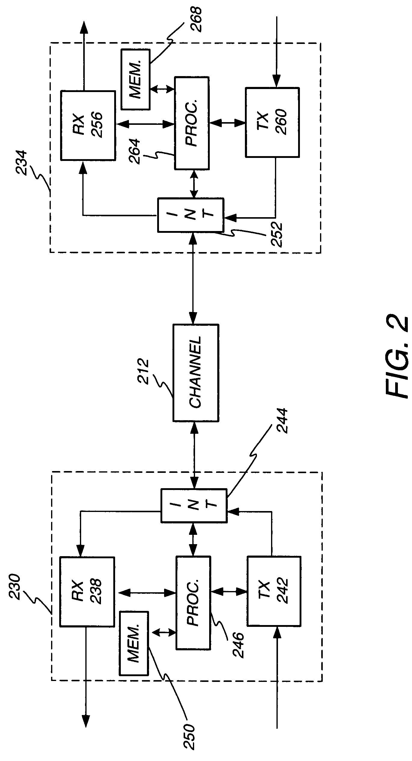
[0034]In reference to FIG. 2, a block diagram of a receiver / transmitter pair is shown. A channel 212 connects a first transceiver 230 to a second transceiver 234. The first transceiver 230 connects to the channel 212 via an interface 244. The interface 244 is configured to isolate the incoming and outgoing signals. The channel 212 may comprise more than one conductor, and hence the interface 244 may perform isolation for each channel based on direction of data flow. The receive module 238 and transmit module 242 may comprise any assembly of hardware, software, or both configured to operate in accordance with the principles described herein.

[0035]The receive module 238 and transmit module 242 communicate with a processor 246. The processor 246 may include or communicate with a memory 250. The processor operates as described below in more detail and as would be understood by one of ordinary skill in the art. The memory 250 may comprise one or more of the following types of memory: RAM...


PUM


Abstract

A crosstalk cancellation system and method is disclosed for use in a multi-channel communication system. Crosstalk which couples between channels is cancelled through use of an in-line FFE filter and in-line delay. A cross-connect system associated with each channel includes a cross-connect delay and cross-connect filter. The cross-connect system generates a cancellation signal for each of the channels, which is routed into a junction. The junction subtracts the cancellation signal from the received signal, which has also been delayed and filtered, to remove unwanted cross-talk. During training, cancellation magnitude is monitored at various delay offsets to determine which offset and corresponding filter coefficients, for each delay, maximizes cancellation. The filters are set with filter coefficients that maximize cancellation. The cross-connect delay with the maximum offset is set to zero and its calculated offset amount is established as the in-line delay offset. The other cross-connect delay offsets are adjusted accordingly.

Description

1. FIELD OF THE INVENTION[0001]The invention relates to communication systems and in particular to a method and apparatus for cross talk cancellation.2. RELATED ART[0002]Modern communication systems achieve data communication between transceivers located at remote locations. To increase data communication rates, communication system cabling arrangements often include numerous conductors in close proximity to transport a signal between remote locations. These systems may be referred to as multi-channel communication systems. Furthermore, communication devices are often constructed on circuit boards containing numerous conductors, traces, or electrical devices. In all of these instances, coupling between channels of a multi-channel communication system may occur, thereby introducing interference into the other channels. This type of interference is generally referred to as crosstalk.[0003]As is commonly understood, crosstalk may be characterized as near end crosstalk (NEXT) and far en...

Claims


Application Information

Patent Timeline
Patent Type & Authority Applications(United States)
IPC IPC(8): H04B15/00
CPCH04B3/32
Inventor PARNABY, GAVIN D.
Owner MARVELL ASIA PTE LTD
Why Eureka
Try Eureka