Cancelling distortion

a technology of distortion and cancellation, applied in the field of cancellation of distortion, can solve the problems of complex required filtering process, inability to achieve the required degree of suppression, etc., to achieve the effect of maximising the cancellation of harmonic or intermodulation signals

Inactive Publication Date: 2008-04-17
TELEFON AB LM ERICSSON (PUBL)
View PDF11 Cites 13 Cited by
  • Summary
  • Abstract
  • Description
  • Claims
  • Application Information

AI Technical Summary

Benefits of technology

[0024] Advantageously, the pre-distortion stage is arranged to suppress third-order intermodulation distortion generated in the harmonic generator network means by impedance mismatching at the further harmonic frequency.
[0026] Advantageously, the pre-distortion stage comprises feedback means to adjust at least one of the in-phase and in-quadrature scaling settings to maximise cancellation of the harmonic or intermodulation signal.
[0038] Advantageously, the method comprises suppressing third-order intermodulation distortion produced in generating the in-phase harmonic signal and the in-quadrature harmonic signal by impedance mismatching at the summed harmonic signal frequency so as to enhance a level of the harmonic signal relative to the intermodulation distortion.
[0040] Advantageously, the method comprises using feedback to adjust at least one of the in-phase and in-quadrature scaling settings to maximise cancellation of the harmonic or intermodulation signal.

Problems solved by technology

Occasionally circumstances, to be described later herein, arise that make this filtering process difficult, or even make it impossible to achieve a required degree of suppression.
Sometimes, however, some of the mixer spurs are too close to the desired signal to be removed by filtering, or even if filtering can remove them, the required filter may be complex, expensive and sizable to implement.
One such mixer spur that in some circumstances can cause problems is a spur at mixer output frequency I=2R−L, i.e. for which m=2 and n=1.
Problems that this mixer spur can cause are exemplified by a case of a down-converter that takes in a high frequency RF signal and mixes it down to a lower frequency.
Such filtering adds complexity, expense and size to a system, and as noted, cannot reject the spur when it is very close to, or overlapping, the wanted mixer output signal, as shown in FIG. 3.
Unfortunately, reducing the input signal level requires more amplification following the mixer to restore the signal level to a given level, so the signal to noise ratio (SNR) of the output signal degrades by X dB.
However, this generally is more expensive.
Such mixers increase cost, circuit size and power consumption.

Method used


Image

  • Cancelling distortion
  • Cancelling distortion
  • Cancelling distortion

Examples


Embodiment Construction

[0053] Throughout the description, identical reference numerals are used to identify like parts.

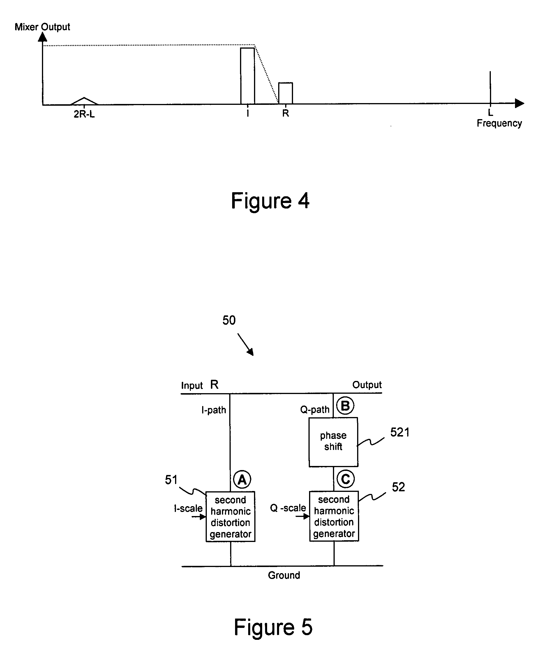
[0054] Referring to FIG. 5, according to the invention there is provided a mixer pre-distortion stage 50 that does not use active amplifying components. The pre-distortion stage 50 comprises two distortion networks in parallel, a first distortion network 51 to produce in-phase (I) harmonic distortion from an input signal of frequency R and a second distortion network 52 to produce in-quadrature (Q) harmonic distortion from the input signal of frequency R. One of the paths, the Q path as illustrated in FIG. 5, although it can be either, includes a phase shifter 521 so that the in-quadrature version of the signal is phase shifted such that the phase of a resultant second harmonic signal of frequency 2R signal relative to the phase of the R signal at point B, at a signal input to the phase shift network 521, is 90° different from the phase of the 2R signal relative to the R signal at point ...


PUM


Abstract

A pre-distortion stage 50 is arranged to cancel a harmonic or intermodulation signal produced from an input signal. The pre-distortion stage includes non-amplifying components comprising a first distortion generator network 51 arranged to produce an in-phase distorted version of the input signal and a second harmonic generator network 52 arranged to produce an in-quadrature distorted version of the input signal. Outputs of the first and second distortion generator networks are combined to produce a combined distortion signal the amplitude and phase of which can be independently adjusted to be of a same amplitude and frequency as, but 180 deg. out of phase with, the harmonic or intermodulation signal generated from the input signal, so as to cancel the harmonic or intermodulation signal. The pre-distortion stage has particular application in cancelling spurs generated in a mixer when the spurs are too close in frequency to a required signal to be efficiently removed by filtering.

Description

FIELD OF THE INVENTION [0001] This invention relates to cancelling distortion and in particular to reducing spurs in a mixer output. BACKGROUND OF THE INVENTION [0002] A known mixer or modulator is a device for shifting a signal from one frequency band to another. A mixer typically uses a multiplication process wherein a wanted variable signal of frequency R, occupying a band of spectrum, and a locally generated single frequency oscillator signal of frequency L, are combined to form sum and difference signals at frequencies R+L and −R+L; a convenient one of these is taken for further processing and the other is removed, typically by filtering. In practical implementations it is usual for such multiplication process to be realised by a non-linearity which also leads to a number of other, unwanted, combinations of R and L, for example, a term formed by a second harmonic of R and L i.e. 2R±L. In most practical implementations these spurious products of the multiplication, known as “spu...

Claims


Application Information

Patent Timeline
Patent Type & Authority Applications(United States)
IPC IPC(8): H04B1/10
CPCH03D7/00
Inventor CURTIS, JOHN S.
Owner TELEFON AB LM ERICSSON (PUBL)
Why Eureka
Try Eureka