
Spring balance

a technology of spring balance and spring, which is applied in the field of spring balance, can solve the problems of inconvenient specialist adjustment of spring balance during their lifetime, increased adjustment difficulty, and spring balance return for

Inactive Publication Date: 2009-08-18
WELLMAN DAVID ANTHONY +1
View PDF17 Cites 5 Cited by
  • Summary
  • Abstract
  • Description
  • Claims
  • Application Information

AI Technical Summary

Benefits of technology

"The invention provides a spring balance that overcomes the disadvantages of previous designs. The spring balance is adjustable by a gearbox with a ratchet mechanism and an over-ride mechanism, allowing for easy adjustment to the preload. The ratchet mechanism allows for easy measurement of the adjustment. The spring balance can be supplied to the window assembly as a single unit, reducing the number of separate components and simplifying the installation process. The top and bottom assemblies each have two housing parts that can be separated, making it easier to fit and secure the components."

Problems solved by technology

Adjustment is made more difficult because both spring balances in each pair must be adjusted together to ensure that the return force is substantially balanced to each side of the window.
The requirement for a specialist to adjust the spring balances during their lifetime is inconvenient at the very least.
Also, adjustment of the spring balances during their lifetime and also during initial assembly of the window is a time consuming task since as above indicated the spring balance must usually be disconnected from the sliding sash to effect adjustment, so that the adjustment is often undertaken in several stages, somewhat on a “trial and error” basis, with the spring balance being re-connected after each trial to learn whether the adjustment is correct.
Even if the manufacturer of the spring balances seeks to avoid the need for adjustment during assembly by setting the desired preload for a particular sliding sash, this is not always successful in practice, and it is believed that around 80% of spring balances require adjustment during window assembly, and most spring balances will require subsequent adjustment during their lifetime.
Since the bottom of the torsion spring cannot rotate this adjustment affects the preload of the torsion spring and thus the return force of the spring balance.
Whilst the disclosure of GB 2,373,813 avoids the major drawbacks of those spring balances which are adjustable at the bottom, the disclosed spring balance has a significant disadvantage.
In practice this is very difficult to achieve because the hexagonal head is necessarily a close fit in the hexagonal opening; if the screwdriver is removed with the hexagonal head not engaging the hexagonal opening the torsion spring will rotate freely so as to remove any preload therein.
The difficulty in achieving satisfactory operation is exacerbated by the requirement to push in the screwdriver against the bias of the return spring, and therefore to reduce the pressure upon the screwdriver as this is removed, in order to allow the return spring to force the hexagonal head of the gear towards (and hopefully into) the hexagonal opening.
Accordingly, whilst the arrangement of GB 2,373,813 appears simple in using the same gear both to adjust the preload and also to prevent free rotation of the torsion spring, in practice this presents significant difficulties.
Another significant disadvantage of the spring balance of GB 2,373,813 (and which is shared by many prior art spring balances) is that there is no upper limit upon the preload which can be set.
Slight over-adjustment is not too great a concern, though any over-adjustment increases the strain upon the torsion spring (and other components) unnecessarily, leading to a reduction in the useful life of the spring balance.
However, significant over-adjustment is a widely-recognised concern, and this can damage a spring balance by exceeding the tolerance either of the torsion spring or other componentry within the spring balance.
Typically, significant over-adjustment manifests itself in damage to the follower bush, which is either forcibly separated from the torsion spring, or else damaged so that it rotates freely upon the spiral rod.
In both cases the effect of the torsion spring is lost and the spring balance must be extensively repaired or replaced.

Method used


Image

  • Spring balance
  • Spring balance
  • Spring balance

Examples


first embodiment

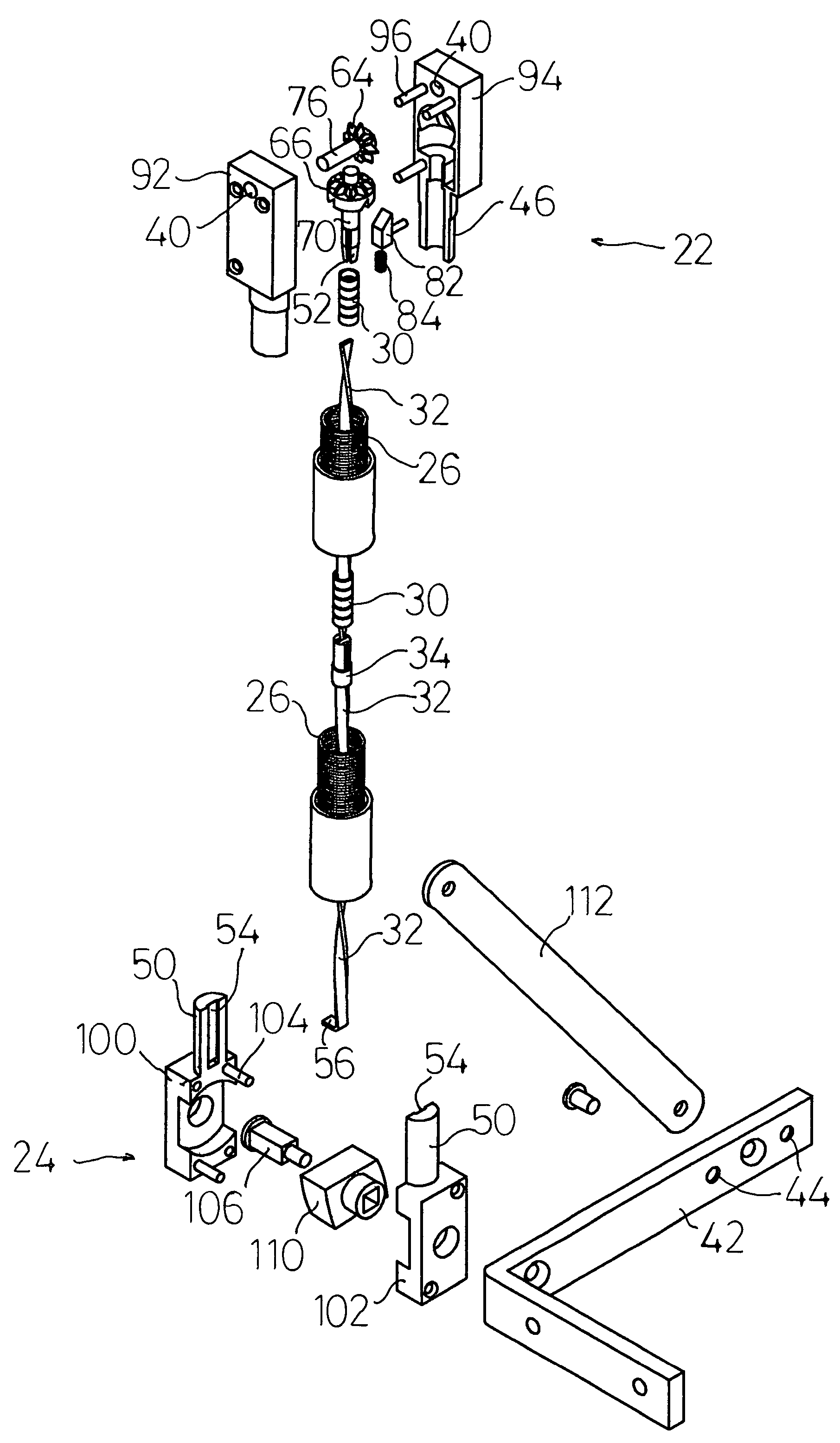
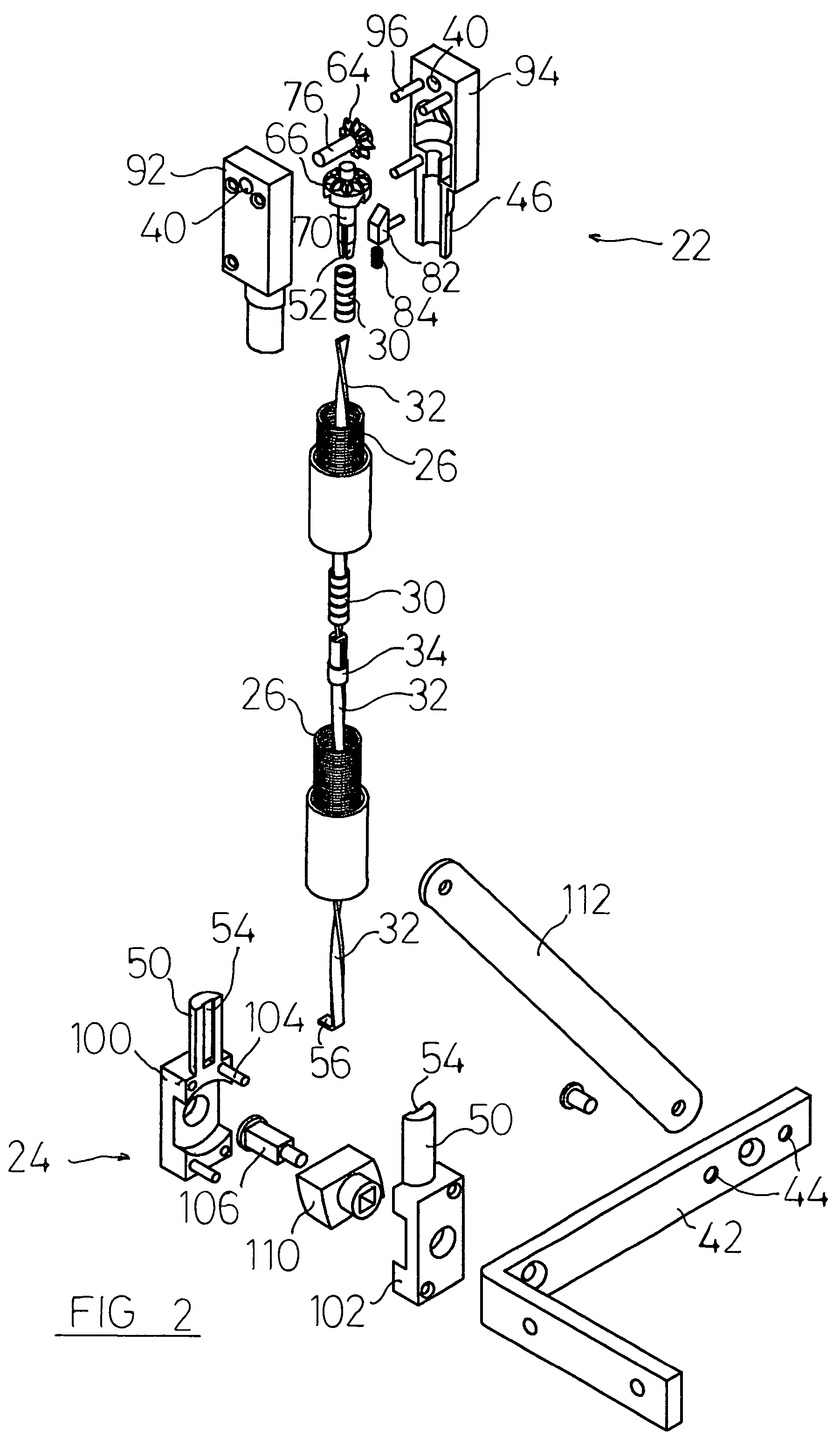
[0039]FIG. 2 shows an exploded view of most components of spring balance according to the invention;

[0040]FIG. 3 shows a cross-sectional view of part of the assembled spring balance of FIG. 2;

[0041]FIG. 4 shows the top part of the cross-sectional view of FIG. 3 in more detail;

[0042]FIG. 5 shows the bottom part of the cross-sectional view of FIG. 3 in more detail;

second embodiment

[0043]FIG. 6 shows an exploded view of the components of top assembly;

[0044]FIG. 7 shows a first view of part of the second embodiment of top assembly, assembled; and,

[0045]FIG. 8 shows a second view of part of the second embodiment of top assembly, assembled.


PUM


Abstract

This invention relates to a spring balance, and in particular to a spring balance for use with a sliding sash window. The invention provides a spring balance comprising a top assembly which is securable to a frame member, a bottom assembly which is securable to a sliding sash, a tension spring connected to the top assembly and to the bottom assembly, a torsion spring, a spiral rod, and a follower bush interconnecting the spiral rod and the torsion spring. The spring balance is adjustable at the top assembly, and includes a limit mechanism for limiting the range of adjustment, the limit mechanism preventing over-adjustment of the spring balance.

Description

FIELD OF THE INVENTION[0001]This invention relates to a spring balance, and in particular to a spring balance for use with a sliding sash window.[0002]In the following description, orientational and directional terms such as “vertical”, “top”, “bottom” etc. refer to the normal orientation of use of the components described (as shown for example in FIG. 3), but the invention places no limitations upon the orientation of the spring balances in use.BACKGROUND OF THE INVENTION[0003]Sliding sash windows comprising two or more window panels, at least one of which can slide in a vertical direction in use to open and close the window, have been in long term and widespread use. During sliding movement, it is necessary for the user to overcome the frictional resistance to movement caused by engagement of the sliding window panel or sliding sash with the channel in which it moves, and also to support the weight of the sliding sash.[0004]To assist the user in moving the sliding sash, it is know...

Claims


Application Information

Patent Timeline
Patent Type & Authority Patents(United States)
IPC IPC(8): E05D13/00
CPCE05D13/1207E05D15/22Y10T16/64E05Y2900/148Y10T16/6298E05Y2600/10
Inventor WELLMAN, DAVID ANTHONYHARRISON, PETER JAMES
Owner WELLMAN DAVID ANTHONY
Learn More