Retractable bungee cord tie down

Inactive Publication Date: 2009-08-18
MADLAND ERIK
View PDF36 Cites 16 Cited by
  • Summary
  • Abstract
  • Description
  • Claims
  • Application Information

AI Technical Summary

Benefits of technology

[0013]In an example of operation, a user secures a free end of the bungee cord to a first securing point such as a loop, a hook, or other structure. The user depresses the button that causes the control arm to disengage from the spool. The spool is then permitted to freely rotate. The user is then able to move the housing, which causes the spool to unwind, and release a length of the bungee cord. Prior to reaching a second securing point a user can cease depressing the button thereby permitting the control arm to reengage the spool. The spool is prevented from rotating and possibly discharging an additional length of the bungee cord. As the user connects the housing to the second securing point the bungee cord is stretched. By stretching the bungee cord a user increases the tension in the bungee cord thereby preve

Problems solved by technology

Ratcheting buckle tie downs are complicated devices that are not easy to operate.
The weight of the buckle often creates a sag in the tie down that can result in the hooks becoming disconnected from the loops or holes.
Additionally, it is not uncommon for the buckle to become positioned (such as between two articles being retained) so that it becomes difficult to operate the ratcheting buckle.
Another problem with the ratcheting buckle is that the repeated ratcheting motion required to increase tension is time consuming and difficult.
Users having limited strength or dexterity find it difficult to use.
Releasing the tension of the ratcheting buckle is often times more difficult than ratcheting the buckle.
Unfortunately, the tension on the

Method used


Image

  • Retractable bungee cord tie down
  • Retractable bungee cord tie down
  • Retractable bungee cord tie down

Examples


Embodiment Construction

[0033]It is to be understood, however, that even though numerous characteristics and advantages of the present invention have been set forth in the foregoing description, together with details of the structure and function of the invention, the disclosure is illustrative only, and changes may be made in detail, especially in matters of shape, size, and arrangement of parts within the principles of the invention to the full extent indicated by the broad general meaning of the terms in which the appended claims are expressed.

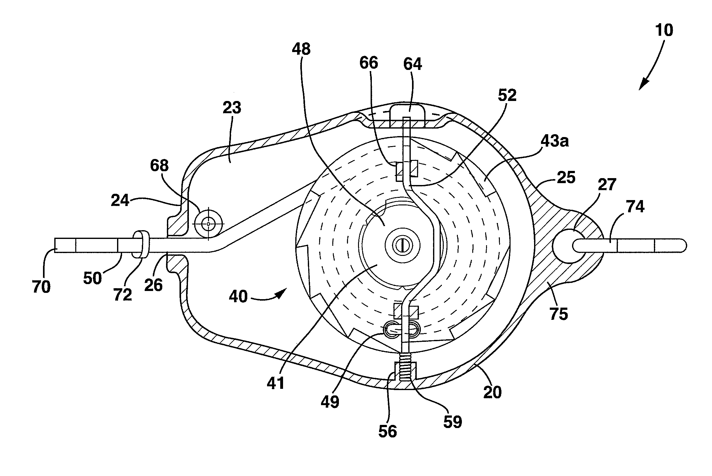
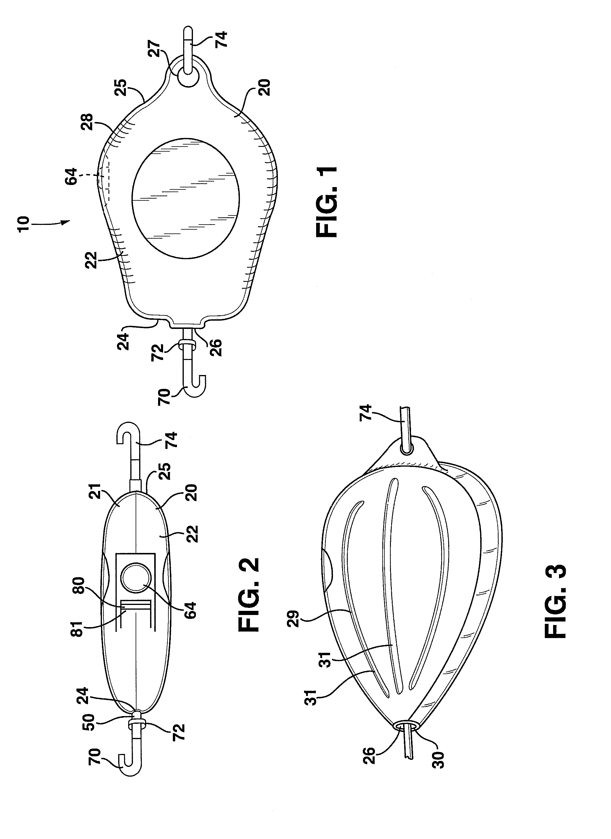
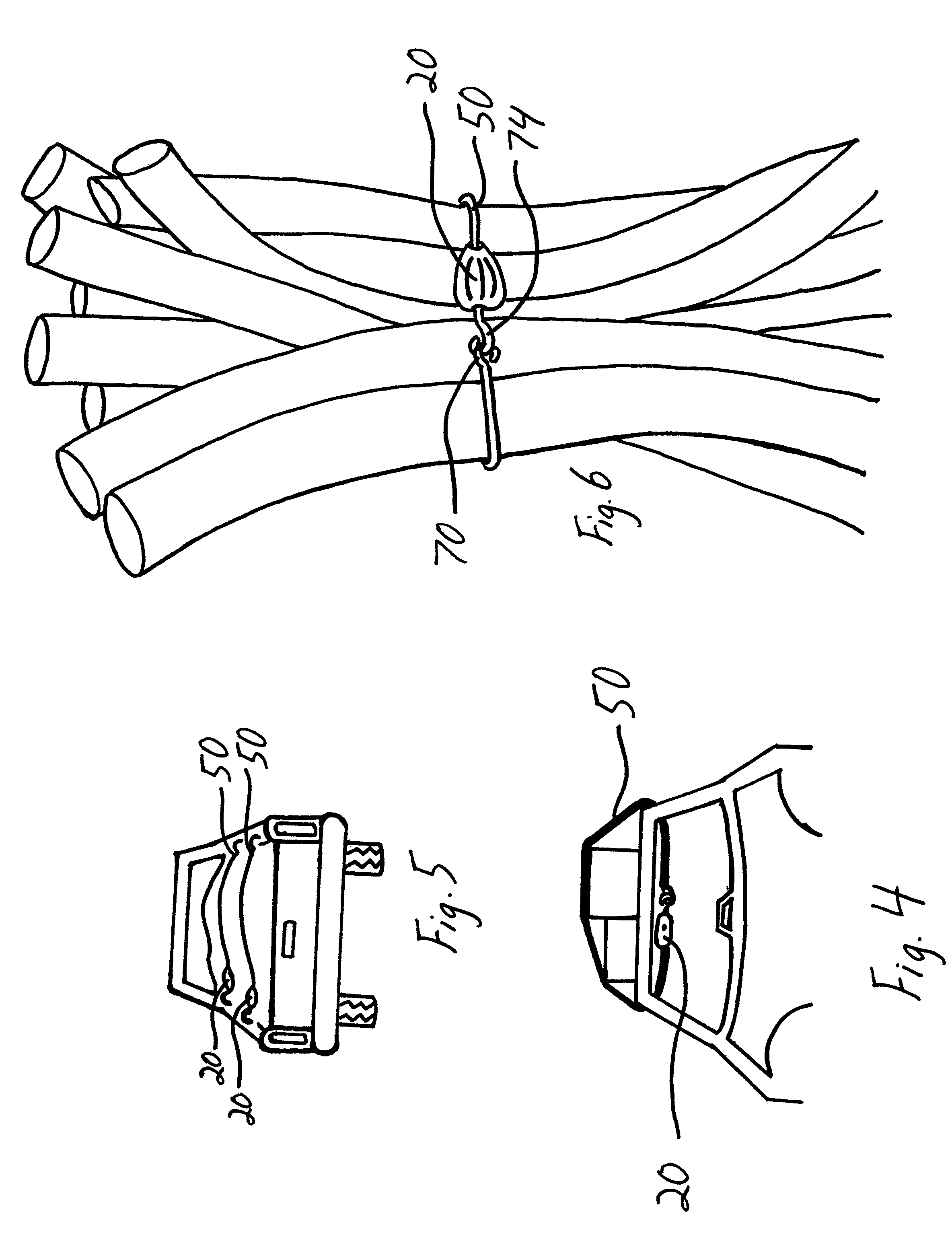
[0034]Referring now to FIG. 1, the retractable bungee cord tie down is indicated by the numeral 10. In an example embodiment of the invention, the retractable bungee cord tie down 10 includes a housing 20, at least partially enclosing a ratcheting mechanism 40 to which is retractably coupled a length of bungee cord material 50. Although a bungee cord material is described as the preferred embodiment of tether, it should be understood that the invention could also ...


PUM


Abstract

A retractable bungee cord tie down having a housing enclosing a ratcheting mechanism and a bungee cord. The bungee cord is wrapped around a spool having a biasing member operatively coupled thereto to permit automatic retraction of the bungee cord into the housing. Operatively coupled to the spool is a control arm that is used to engage and disengage spool movement and thus movement of the bungee cord into or out of the housing. A button connected to the control arm permits a user to secure items by securing the bungee cord first and then operating or moving the housing to another secure location.

Description

CLAIM OF PRIORITY[0001]The present invention claims the benefit of U.S. Provisional Application Ser. No. 60 / 765,570 filed on Feb. 6, 2006 and incorporated herein in its entirety by reference.BACKGROUND OF THE INVENTION[0002]1. Field of the Invention[0003]The present invention relates to an apparatus for restraining movement of cargo or items with respect to a non-moveable structure or themselves. More particularly, the present invention is related to a retractable bungee cord tie down that is easily operated with a single hand of a user.[0004]2. Description of Related Art[0005]Tie downs for securing items is widely known. The most conventional tie down is the buckle tie down. The buckle tie down includes an adjustable strap operatively woven in a ratcheting buckle. The adjustable strap includes a hook for attaching to a loop or hole structure of a vehicle or to the strap itself A leader or fixed strap and hook is typically connected to the ratcheting buckle. The ratcheting buckle in...

Claims


Application Information

Patent Timeline
IPC IPC(8): B66D3/00
CPCB66D3/04B66D5/34Y10T24/2147
Inventor MADLAND, ERIK
Owner MADLAND ERIK
Why Eureka
Try Eureka