Rotary bar screen device

a technology of rotary bar and screen, which is applied in the direction of moving filter element filter, filtration separation, separation process, etc., can solve the problems of excessive occupying space, considerable difficulty in maintenance work, and rotary bar screen device, so as to maximize the effective area for passing seawater and increase the effective area , the effect of increasing the effective area

Active Publication Date: 2009-08-18
COWAY ENTECH CO LTD
View PDF12 Cites 10 Cited by
  • Summary
  • Abstract
  • Description
  • Claims
  • Application Information

AI Technical Summary

Benefits of technology

[0010]One object of the present invention is to provide a rotary bar screen device with an increased effective area, for maximizing the effective area for passing seawater.
[0011]Another object of the present invention is to provide a rotary bar screen device with an increased effective area, for picking up and simply and conveniently removing foreign materials such as floating materials from water.
[0012]A further another object of the present invention is to provide a rotary bar screen device with an increased effective area, for minimizing a space for installation in a water intake structure.

Problems solved by technology

Accordingly, the conventional rotary bar screen device has a drawback that it excessively occupies a space for installation in a water intake structure, and has a considerable difficulty in a maintenance work.
Accordingly, there is a drawback of sufficiently guaranteeing an introduction passage for passing the seawater.

Method used


Image

  • Rotary bar screen device
  • Rotary bar screen device
  • Rotary bar screen device

Examples


Embodiment Construction

[0026]Reference will now be made in detail to the preferred embodiments of the present invention, examples of which are illustrated in the accompanying drawings. Wherever possible, the same reference numerals will be used throughout the drawings to refer to the same or like parts.

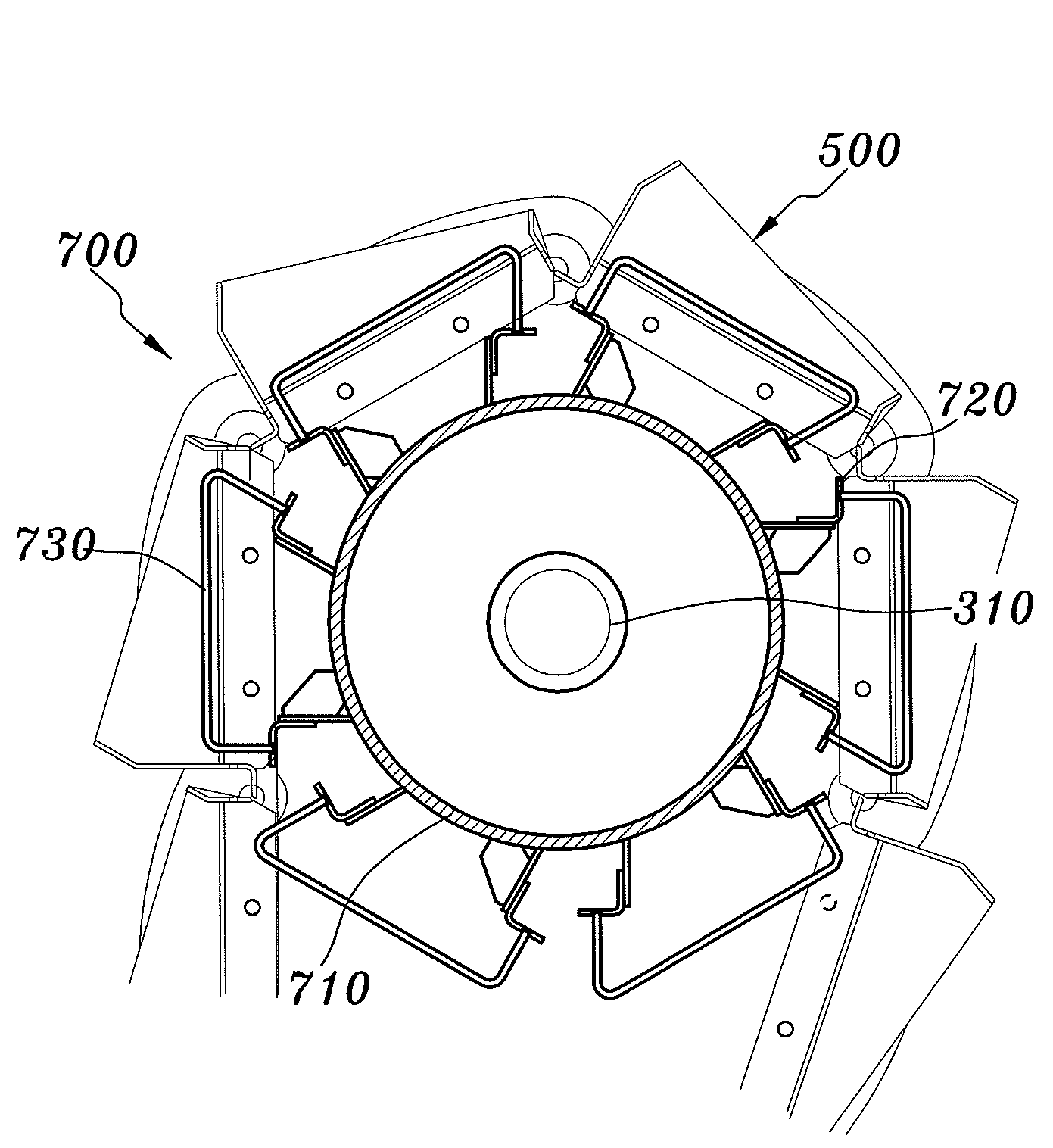
[0027]FIG. 4 is a front diagram illustrating a rotary bar screen device with an increased effective area according to the present invention. FIG. 5 is a side diagram illustrating the rotary bar screen device of FIG. 4. As shown in FIGS. 4 and 5, the inventive rotary bar screen device includes a support frame 100, a driving motor 200, a transfer chain 400 connecting to driving and driven sprockets 300 and 320, a screen bucket 500, a seal plate 600, a removal unit 700, and a slide plate 810.

[0028]The driving motor 200 is fixedly installed at an upper end of the support frame 100, and transmits a driving force. The driving motor 200 is of a structure in which it can transmit a rotary force to the driving sproc...


PUM

PropertyMeasurementUnit
driving forceaaaaaaaaaa
tensionsaaaaaaaaaa
timeaaaaaaaaaa

Abstract

Provided is a rotary bar screen device. The device includes a driving motor, an up / down pair of driving and driven sprockets, left and right transfer chains, a plurality of screen buckets, a removal unit, and a slide plate. The driving motor is provided over a support frame, and transmits a driving force. The driving and driven sprockets are driven by the driving force. The left and right transfer chains connect the driving and driven sprockets with each other while circulatively moving. The plurality of screen buckets are provided between the left and right transfer chains. The removal unit is provided between the left and right driving sprockets. The slide plate guides the foreign materials dropping from the screen buckets.

Description

BACKGROUND OF THE INVENTION[0001]1. Field of the Invention[0002]The present invention relates to a rotary bar screen device, and more particularly, to a rotary bar screen device with an increased effective area, for maximizing the effective area for passing seawater and simply and conveniently picking up and removing foreign materials such as floating matters from water.[0003]2. Description of the Related Art[0004]In general, a seawater refreshing plant or an electricity generating plant is equipped with a rotary bar screen device at its water intake port to filter a shellfish or an oceanic life and foreign materials such as various floating waste materials out of seawater because it takes and uses the seawater as a raw water or a cooling water of a cooling system.[0005]FIG. 1 illustrates a conventional rotary bar screen device. As shown in FIG. 1, a support frame 10 is installed in a concrete structure of a water intake facility, and driving sprockets 30 are installed at both sides...

Claims


Application Information

Patent Timeline
Patent Type & Authority Patents(United States)
IPC IPC(8): E03F5/14
CPCB01D33/333C02F1/265C02F1/40C02F2303/24C02F2201/002C02F2103/08
Inventor CHANG, MYUNG KEUN
Owner COWAY ENTECH CO LTD
Why Eureka
Try Eureka