Inductive angular-position sensor

Inactive Publication Date: 2009-08-18
SAPPEL SA
View PDF4 Cites 9 Cited by
  • Summary
  • Abstract
  • Description
  • Claims
  • Application Information

AI Technical Summary

Benefits of technology

[0005]A second solution uses capacitive sensors. The rotating part is then equipped with a partially metallized disk. In the vicinity of and parallel to this disk, a special arrangement of metallized zones, whose different capacitive couplings vary based on the position of the disk, is found. The observation of these capacitive couplings makes it possible to detect the rotation of the rotating part, therefore the flo

Problems solved by technology

The capacitive sensors have the drawback of having to be very close to the rotating disk.
In addition, they are easily disturbed by any geometric change or any var

Method used


Image

  • Inductive angular-position sensor
  • Inductive angular-position sensor
  • Inductive angular-position sensor

Examples


Embodiment Construction

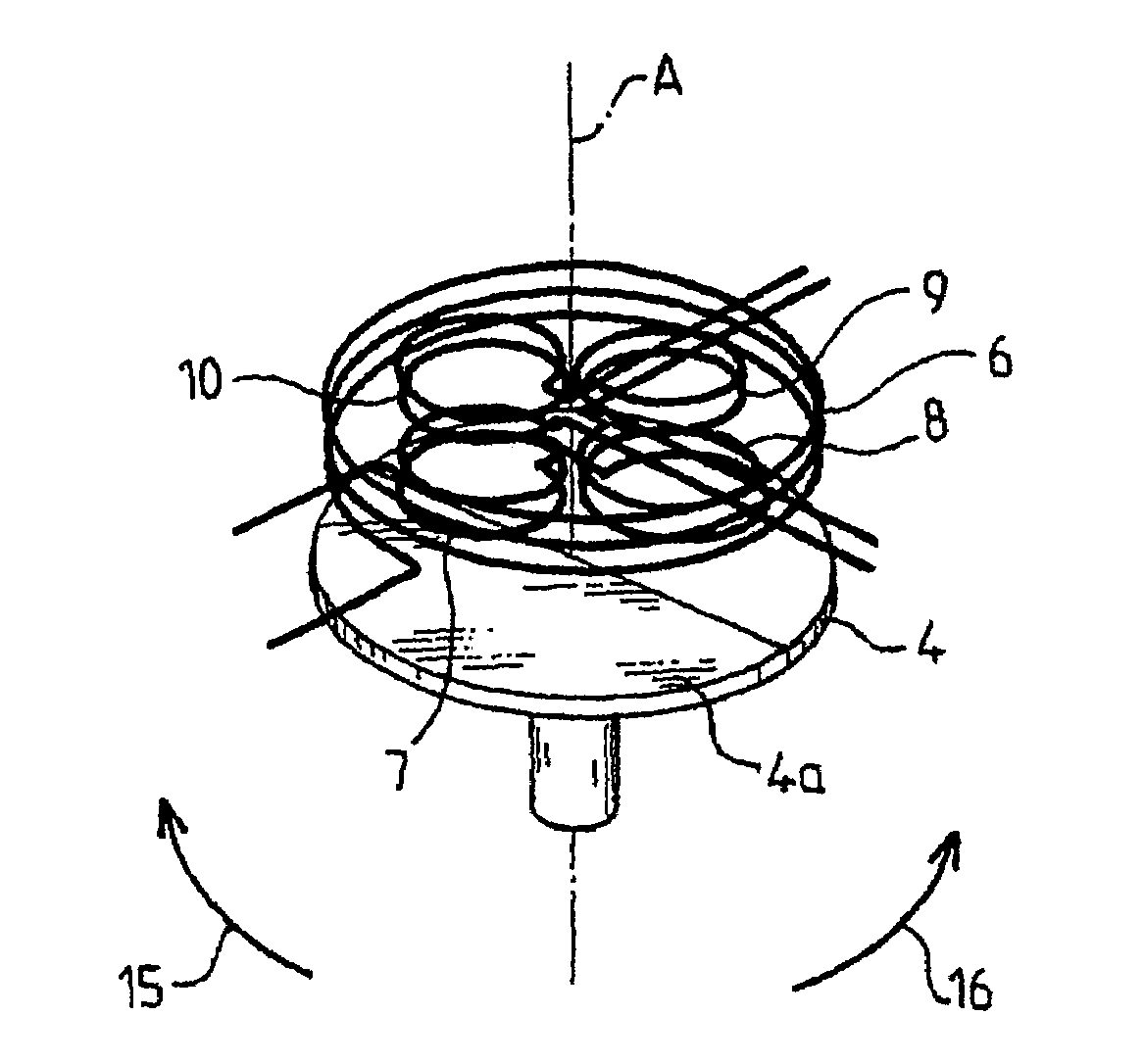
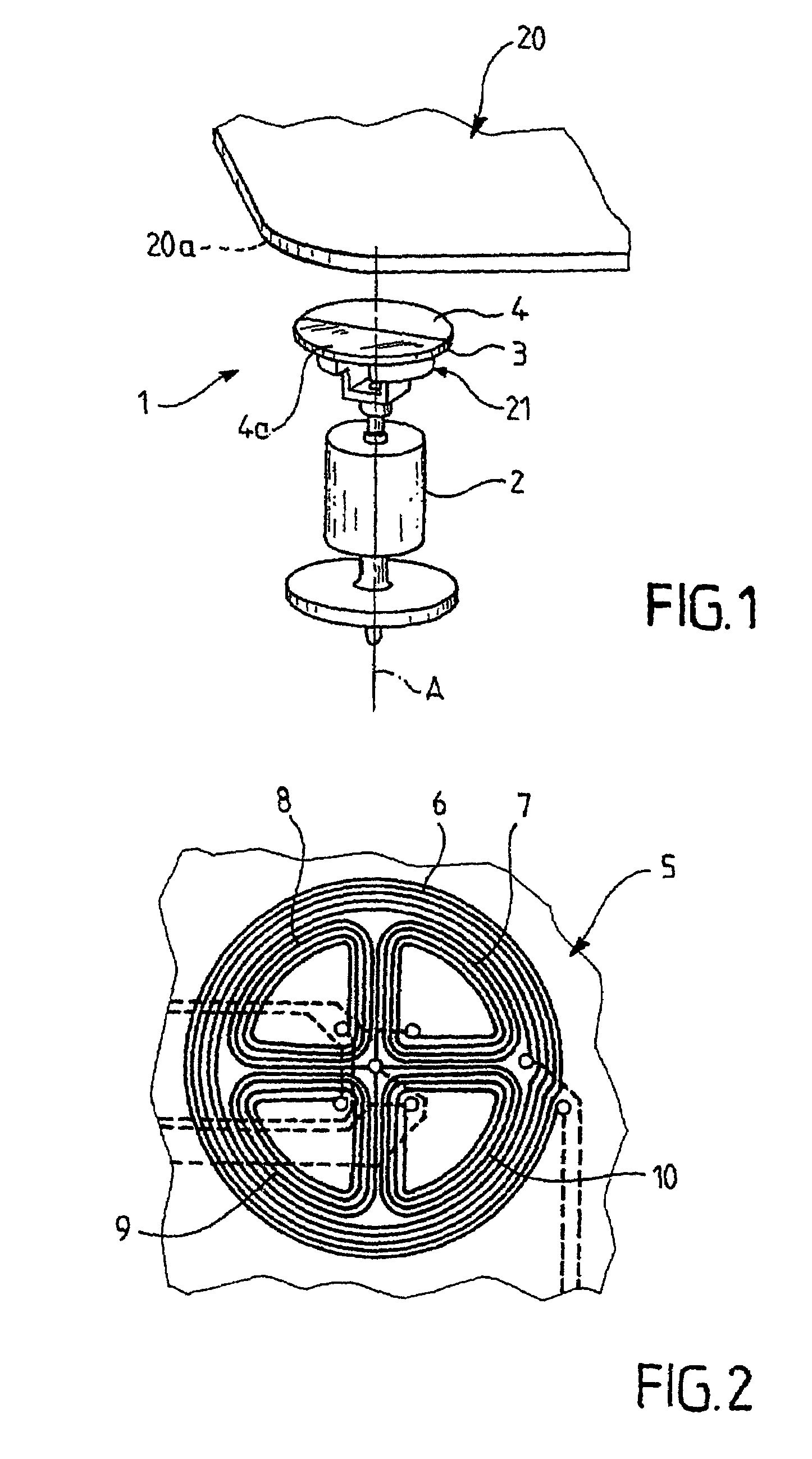
[0024]With reference to FIG. 1, a rotating moving body 2 is shown that is driven in rotation along its axis of revolution A, for example by the flow of a fluid (not shown). An inductive angular-position sensor 1 comprises a stator 20 and a rotor 21. The stator 20 and the rotor 21 can be moved angularly relative to one another along axis A. It will be noted that the use of the term stator does not imply that the stator 20 has a fixed orientation.

[0025]The rotor 21 comprises a rotating disk 3. The rotating disk 3 is arranged on the rotating moving body 2, such that the rotating disk 3 is integral in rotation along axis A of the rotating moving body 2. The flat surface 4 of the disk 3 that is opposite to the rotating moving body 2 is partially metallized. For example, a half-disk 4a is metallized.

[0026]The stator 20 comprises a printed circuit 5 (FIG. 2). The printed circuit 5 is arranged at the right and close to the disk 3, essentially parallel to the surface 4.

[0027]With reference t...


PUM


Abstract

Inductive angular-position sensor, including a partially metallized disk that moves in rotation around its axis of revolution; and a stator that includes a primary coil and several secondary coils, whereby the secondary coils are arranged essentially symmetrically in pairs relative to the axis of revolution, so as to form one or more pairs of secondary coils, whereby the secondary coils of each pair are connected, on the one hand, to one another, in series and in phase opposition relative to one another, and, on the other hand, to the terminals of a measuring element that can generate an output signal that depends on the voltage at the terminals of the pair.

Description

BACKGROUND OF THE INVENTION[0001]This invention has as its object an inductive angular-position sensor.[0002]It is common to use a mechanical part that rotates based on the flow of a fluid so as to measure flow rate. In general, an angular-position sensor detects the rate of rotation of the rotating part so as to allow an electronic processing of the information. This invention is particularly suited to this application, although it is not limited thereto.[0003]Several solutions are known for detecting an angular position.[0004]A first solution uses magnetic sensors. The rotating part is then equipped with a small permanent magnet whose magnetic field actuates the electric contact of a Reed ampoule that is arranged in the vicinity. The switching of this electric contact is therefore representative of the flow of the liquid. Certain sensors rely on several ampoules to as to make it possible, for example, to detect the direction of rotation of the rotating part, therefore the flow dir...

Claims


Application Information

Patent Timeline
IPC IPC(8): G01B7/30
CPCG01D5/2053G01P3/488
Inventor BACH, GUYDOCKWILLER, BERNARD
Owner SAPPEL SA
Why Eureka
Try Eureka