Aircraft door arrangement

a technology for aircraft and doors, applied in door/window fittings, transportation and packaging, wing accessories, etc., can solve the problems of short and clear cut, and achieve the effect of simple and effectiv

Active Publication Date: 2009-08-25
AIRBUS HELICOPTERS DEUT GMBH
View PDF14 Cites 27 Cited by
  • Summary
  • Abstract
  • Description
  • Claims
  • Application Information

AI Technical Summary

Benefits of technology

[0004]An object of the present invention is to provide a simple and effective aircraft door arrangement that avoids one or more of the above-mentioned drawbacks associated with the state of the art.

Problems solved by technology

This translates into short and clear-cut load paths or load flows.

Method used


Image

  • Aircraft door arrangement
  • Aircraft door arrangement
  • Aircraft door arrangement

Examples


Embodiment Construction

[0022]For purposes of avoiding duplications in the description that follows as well as in the figures, parts and components that are the same will be designated with the same reference numerals insofar as no further differentiation is necessary.

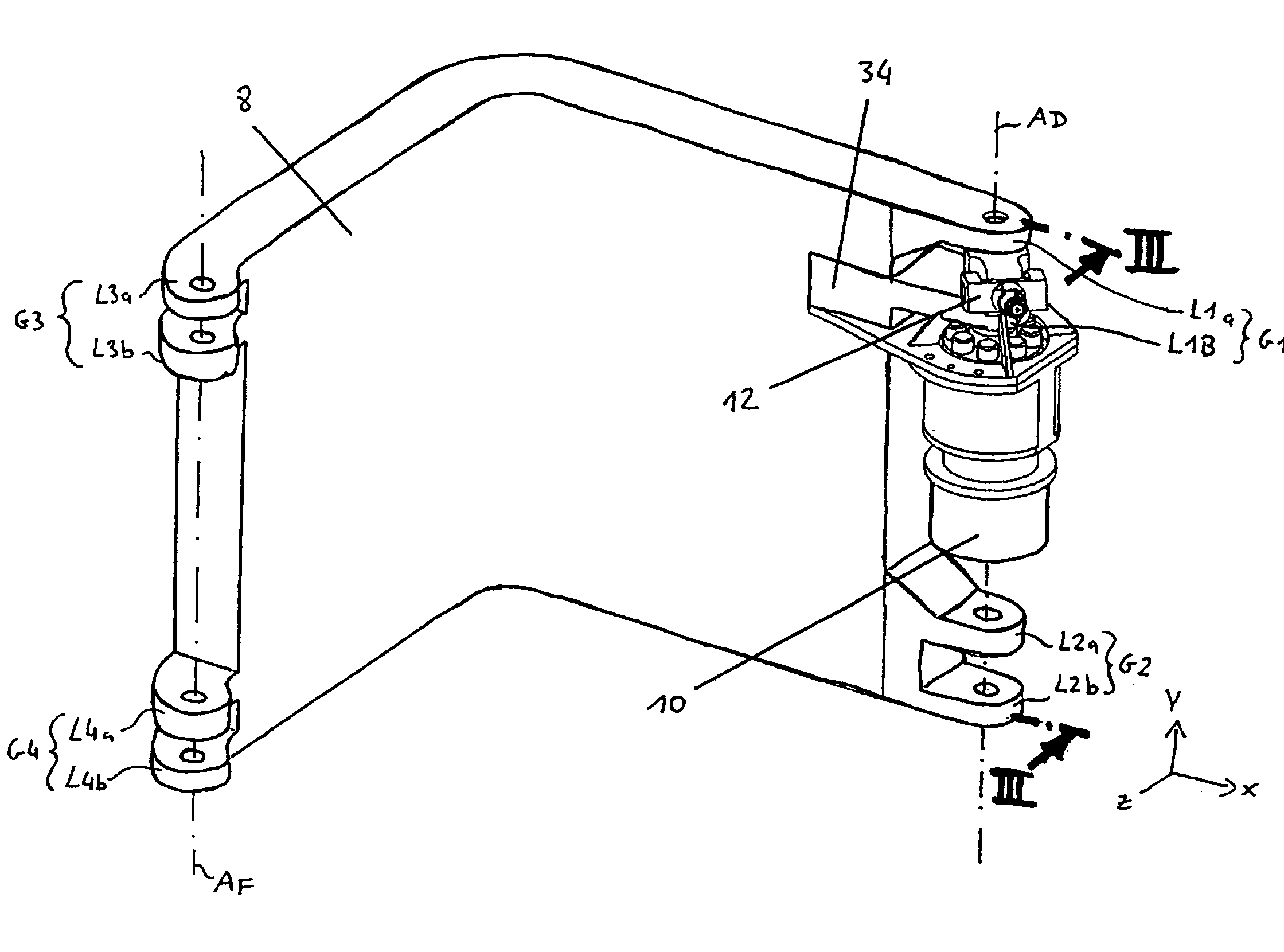
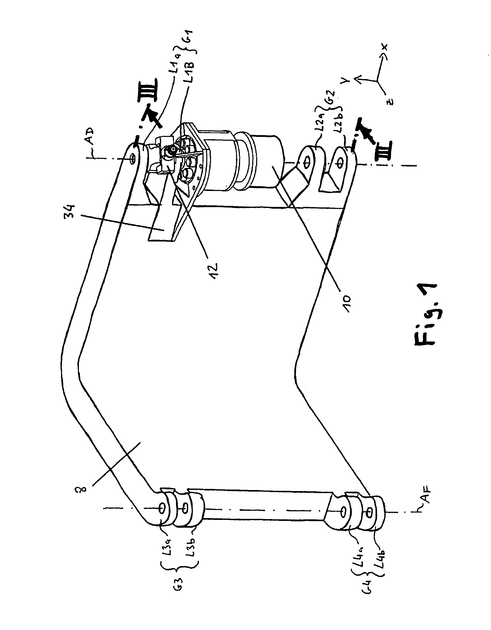
[0023]An aircraft door arrangement according to the invention as shown in FIG. 5 (here, for an airplane with a pressurized cabin), in the present embodiment comprises an airplane door 2 designed as a passenger door, with a door structure 4 and a door frame 6 that is formed by a frame structure of the fuselage. Moreover, the door arrangement comprises a support arm 8 that is preferably made of fiber composite material (for instance, carbon fiber reinforced plastic—CRP), of an aluminum alloy or of another suitable material or material combination. The support arm 8 has a pivoting axis AD on the door side, on which the door 2 is mounted so as to swivel laterally, while it has a pivoting axis AF on the frame side, on which the support arm 8 is mo...


PUM


Abstract

An aircraft door arrangement, especially for an airplane, comprising a door; a door frame; a support arm with a pivoting axis on the door side, on which the door is mounted so as to swivel, and a pivoting axis on the frame side, on which the support arm is mounted so as to swivel on the door frame, whereby at least the pivoting axis on the door side is defined by two articulated joints positioned at a distance from each other in the vertical direction of the support arm, of which articulated joints at least one articulated joint has two bearings positioned at a distance from each other in the vertical direction; a pivoting drive that is arranged in the area of the support arm on the door side and that serves to swivel the door; and a driven element that is coupled to the pivoting drive and to the door and that transmits an actuating movement of the pivoting drive to the door. The aircraft door arrangement is characterized in that one of the two bearings of at least one of the articulated joints on the frame side is configured as a pivoting drive mounting to which the pivoting drive is attached.

Description

[0001]The present invention relates to an aircraft door arrangement, especially for an airplane and, in turn, especially for an airplane with a pressurized cabin.BACKGROUND[0002]From various types of aircraft that have been in operation for a long time, an aircraft door arrangement is known that comprises a door, a door frame and a support arm. This support arm has a pivoting axis on the door side, on which the door is mounted so as to swivel, and it has a pivoting axis on the frame side, on which the support arm is mounted so as to swivel on the door frame. The pivoting axis on the door side is defined by two articulated joints positioned at a distance from each other in the vertical direction of the support arm, each articulated joint comprising two bifurcated bearings which are positioned at a distance from each other in the vertical direction and which are each formed by two eye plates. The door arrangement has a pivoting drive 104 that serves to swivel the door. This pivoting d...

Claims


Application Information

Patent Timeline
Patent Type & Authority Patents(United States)
IPC IPC(8): B64C1/14
CPCB64C1/143B64C1/1407
Inventor WIERS, ANDREASSUCHY, RAINERKUNZE, STEFFENSTEER, MATTHIAS
Owner AIRBUS HELICOPTERS DEUT GMBH
Why Eureka
Try Eureka