

Quick swap load port
a load port and quick swap technology, applied in the field of material processing, can solve the problems of insufficient work in process (wip) at the tool, insufficient transport capacity or scheduling flexibility, and less than optimal solutions, and achieve the effect of reducing the load on the material handling system
- Summary
- Abstract
- Description
- Claims
- Application Information
AI Technical Summary
Benefits of technology
Problems solved by technology
Method used
Image

Examples
Embodiment Construction
[0020]Although the following detailed description contains many specific details for the purposes of illustration, anyone of ordinary skill in the art will appreciate that many variations and alterations to the following details are within the scope of the invention. Accordingly, the exemplary embodiments of the invention described below are set forth without any loss of generality to, and without imposing limitations upon, the claimed invention.
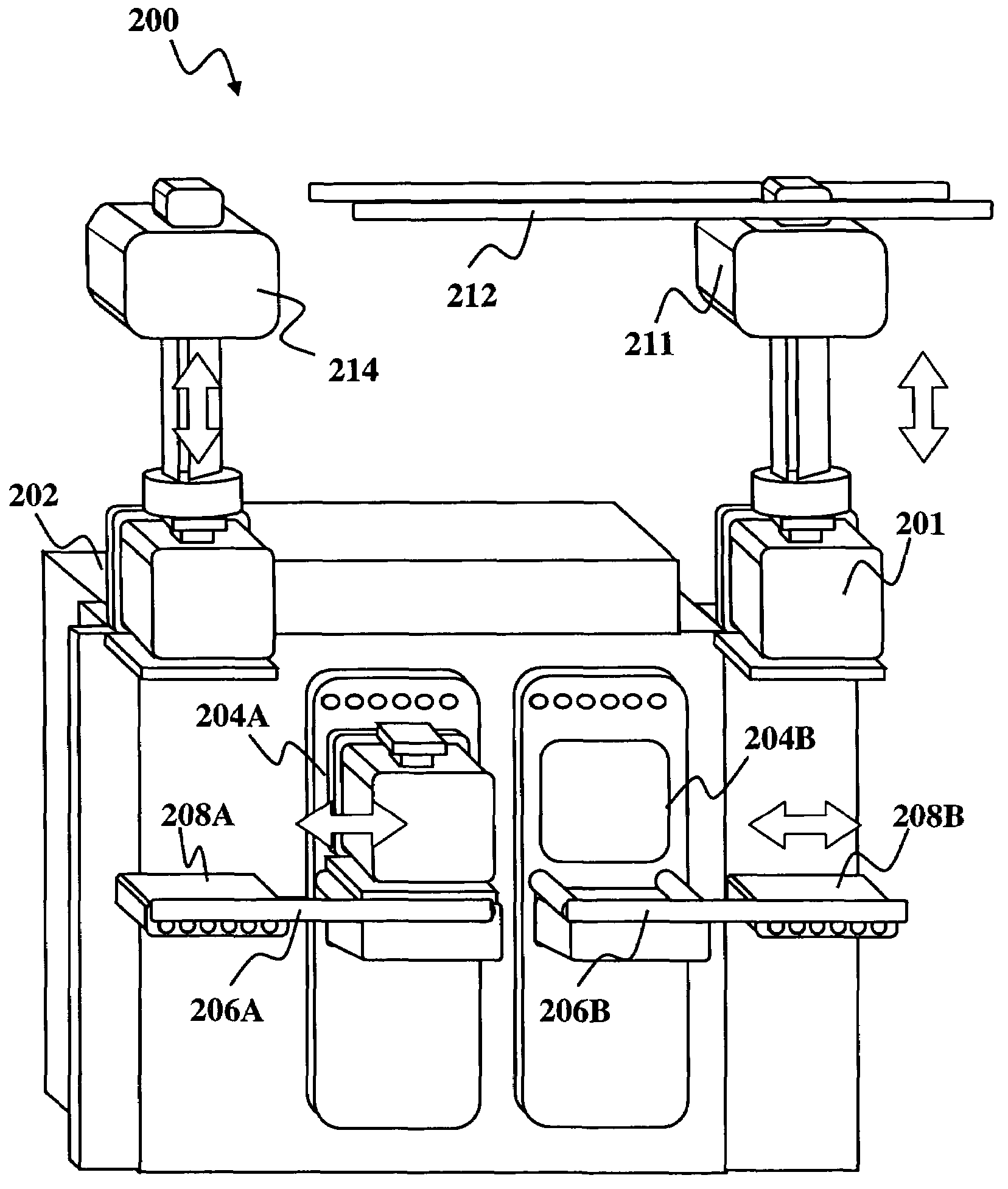
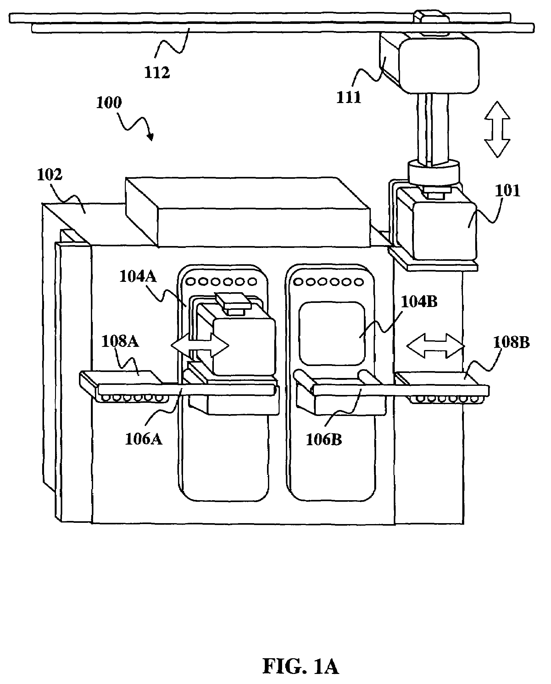
[0021]The inventors have recognized that a wafer processing system does not need four (or more load ports. Instead, by providing additional storage and the ability to drop off FOUPs to a tool or pick them up from the tool while additional FOUPs are being processed tool efficiency can be enhanced.
[0022]According to an embodiment of the present invention, a load port design allows a new FOUP to be lowed to the load-port prior to the completed FOUP being removed. This localized buffering or swapping can be accomplished with a variety of motions...
PUM
 Abstract
Description
Claims
Application Information