
Motor and manufacturing method thereof

a manufacturing method and motor technology, applied in the field of motors, can solve problems such as motor malfunction, and achieve the effect of reducing the speed of rotation

Active Publication Date: 2009-08-25
DENSO CORP
View PDF10 Cites 3 Cited by
  • Summary
  • Abstract
  • Description
  • Claims
  • Application Information

AI Technical Summary

Benefits of technology

[0008]The present invention addresses the above disadvantages. Thus, it is an objective of the present invention to provide a motor, which alleviates a mechanical stress applied to an electrical connection of a control circuit member to limit malfunctioning of the motor. It is another objective of the present invention to provide a manufacturing method of such a motor.
[0011]To achieve the objectives of the present invention, there is provided a manufacturing method of a motor. According to the manufacturing method, a base of a control circuit member, which holds a plurality of terminals, is installed to a brush holder of a motor main body, which holds a plurality of power supply brushes, so that the base of the control circuit member is supported by the brush holder, and a drive control IC of the control circuit member, which controls rotation of a motor main body, is electrically connected to the brush holder through the plurality of terminals. Then, the motor main body having the brush holder is assembled with a gear housing, which receives a speed reducing mechanism that reduces a speed of rotation generated in the motor main body and outputs the rotation of the reduced speed, after the installing of the base of the control circuit member to the brush holder.

Problems solved by technology

Thus, in some situations, electrical connections of the circuit board may be broken to cause malfunctioning of the motor.

Method used


Image

  • Motor and manufacturing method thereof
  • Motor and manufacturing method thereof
  • Motor and manufacturing method thereof

Examples


first embodiment

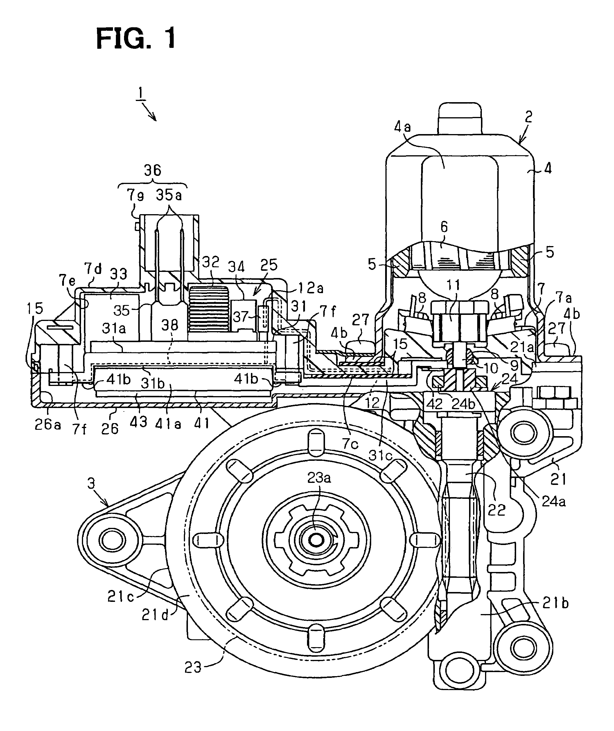
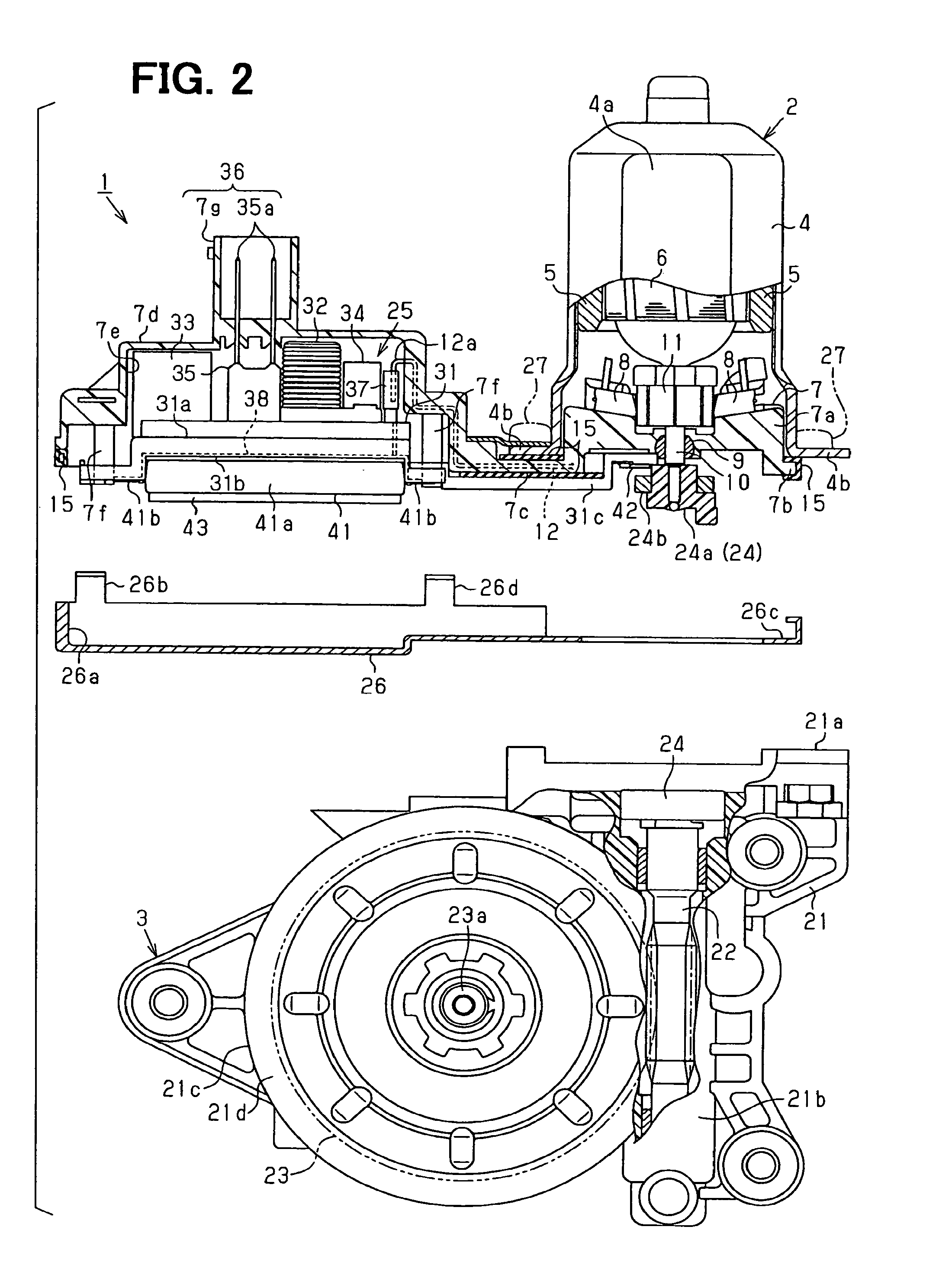
[0020]A motor for a vehicle power window system according to a first embodiment of the present invention will be described with reference to the accompanying drawings.

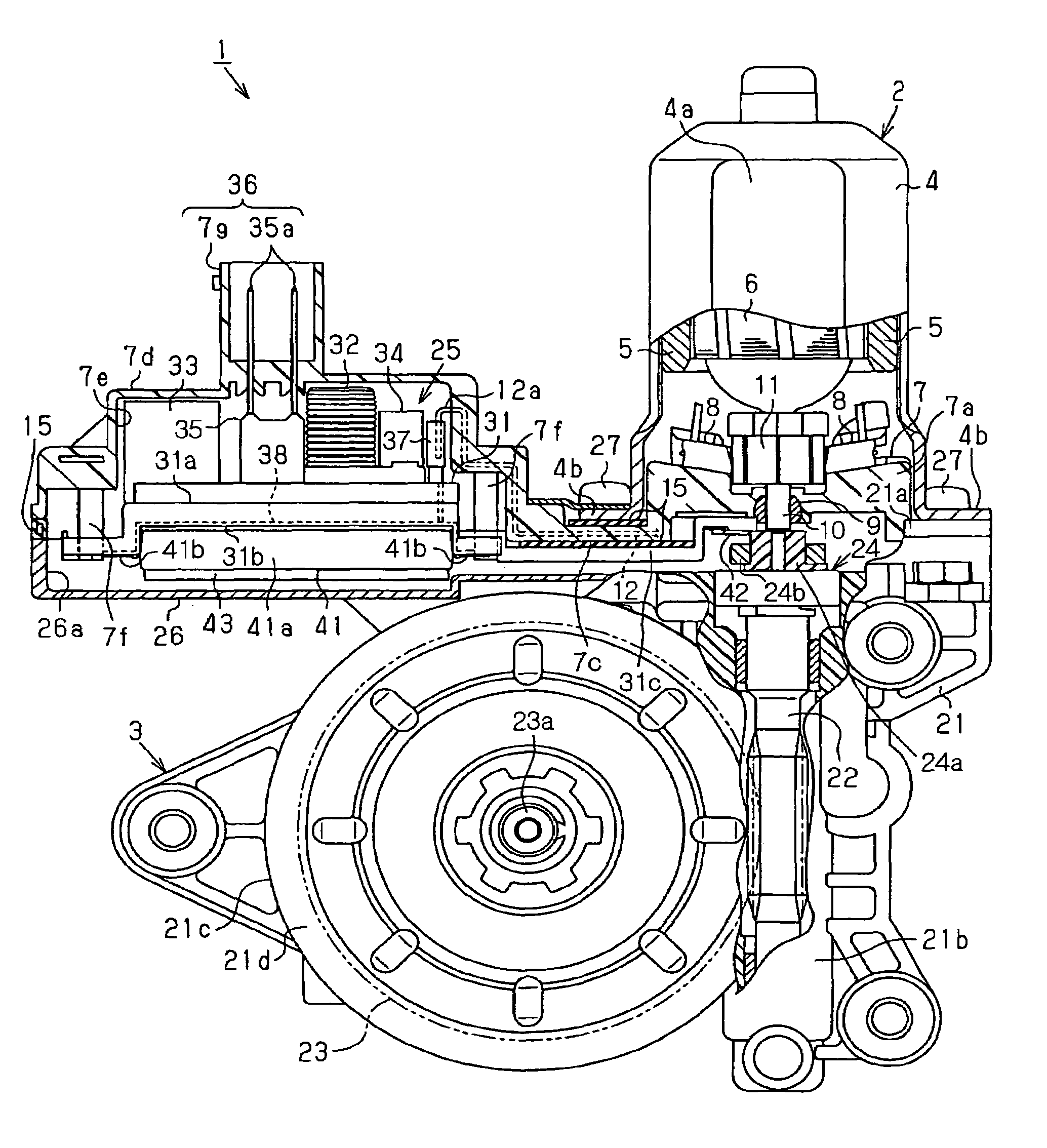
[0021]As shown in FIGS. 1 and 2, the motor 1 of the present embodiment includes a motor main body 2 and a speed reducer (a speed reducing mechanism) 3. The motor main body 2 rotates upon energization thereof. The speed reducer 3 reduces a speed the rotation generated in the motor main body 2 and outputs the rotation of the reduced speed.

[0022]The motor main body 2 includes a yoke housing (hereinafter, simply referred to as a yoke) 4, two permanent magnets 5, an armature 6, a brush holder 7 and two power supply brushes 8. The yoke 4 is shaped into a generally flattened cup-shaped body having a closed bottom. The magnets 5 are secured to an inner peripheral surface of the yoke 4. The armature 6 is rotatably supported in the yoke 4.

[0023]The brush holder 7 is made of a resin material and includes a holder main body 7a, a ...

second embodiment

[0056]A motor for a vehicle power window system according to a second embodiment of the present invention will be described with reference to the accompanying drawings.

[0057]As shown in FIG. 4, the motor 101 of the present embodiment includes a motor main body 102 and a speed reducer (a speed reducing mechanism) 103. The motor main body 102 rotates upon energization thereof. The speed reducer 103 reduces a speed of the rotation generated in the motor main body 102 and outputs the rotation of the reduced speed.

[0058]As shown in FIGS. 4 and 5, the motor main body 102 includes a yoke housing (hereinafter, simply referred to as a yoke) 104, two permanent magnets 105 (FIG. 5), an armature 106, a brush holder 107 and two power supply brushes 108. The yoke 104 is shaped into a generally flattened cup-shaped body having a closed bottom. The magnets 105 are secured to an inner peripheral surface of the yoke 104. The armature 106 is rotatably supported in the yoke 104.

[0059]The brush holder 1...


PUM


Abstract

A motor main body includes a brush holder, which holds a plurality of power supply brushes. A control circuit member includes a drive control IC, which controls rotation of the motor main body, and a base, which holds a plurality of terminals that electrically connects between the drive control IC and the plurality of power supply brushes of the brush holder. The base is supported by the brush holder.

Description

CROSS REFERENCE TO RELATED APPLICATION[0001]This application is based on and incorporates herein by reference Japanese Patent Application No. 2005-325440 filed on Nov. 9, 2005 and Japanese Patent Application No. 2006-234317 filed on Aug. 30, 2006.BACKGROUND OF THE INVENTION[0002]1. Field of the Invention[0003]The present invention relates to a motor that has a control circuit member, in which a drive control IC is installed, and also relates to a manufacturing method of such a motor.[0004]2. Description of Related Art[0005]One previously proposed motor, which is used in, for example, a power window system, includes a motor main body, a speed reducer and a control circuit member. The motor main body rotates upon energization thereof. The speed reducer reduces a speed of rotation generated in the motor main body and outputs the rotation of the reduced speed. The control circuit member controls the rotation of the motor main body. Recently, there has been proposed a control circuit mem...

Claims


Application Information

Patent Timeline
Patent Type & Authority Patents(United States)
IPC IPC(8): H02K11/00
CPCH02K5/148H02K5/225H02K11/026H02K11/0021H02K11/0084H02K7/1166H02K11/215H02K11/38
Inventor SAKOHIRA, KAZUTAKAYAMAMOTO, HIROAKINAKAGAWA, ATSUSHI
Owner DENSO CORP
Learn More