
Single axis inertial sensor with suppressed parasitic modes

a single-axis inertial sensor and parasitic mode technology, applied in the field ofinertial sensor devices, can solve the problems of limited sensitivity of z-axis teeter-totter accelerometer sensors

Active Publication Date: 2020-10-20
NXP USA INC
View PDF18 Cites 0 Cited by
  • Summary
  • Abstract
  • Description
  • Claims
  • Application Information

AI Technical Summary

Benefits of technology

This approach improves sensitivity, reduces noise, and increases resistance to electromagnetic interference, providing better linearity, thermal coefficient of offset stability, and reduced stiction-related malfunctions.

Problems solved by technology

Such Z-axis teeter-totter accelerometer sensors may suffer from limited sensitivity due to a non-constant gap width change resulting from the teeter-totter motion.

Method used


Image

  • Single axis inertial sensor with suppressed parasitic modes
  • Single axis inertial sensor with suppressed parasitic modes
  • Single axis inertial sensor with suppressed parasitic modes

Examples


Embodiment Construction

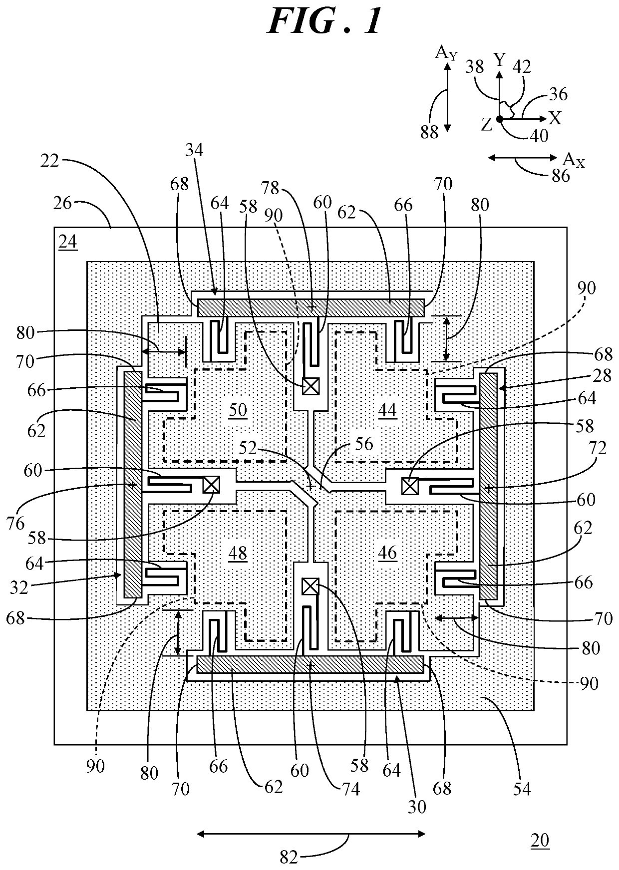
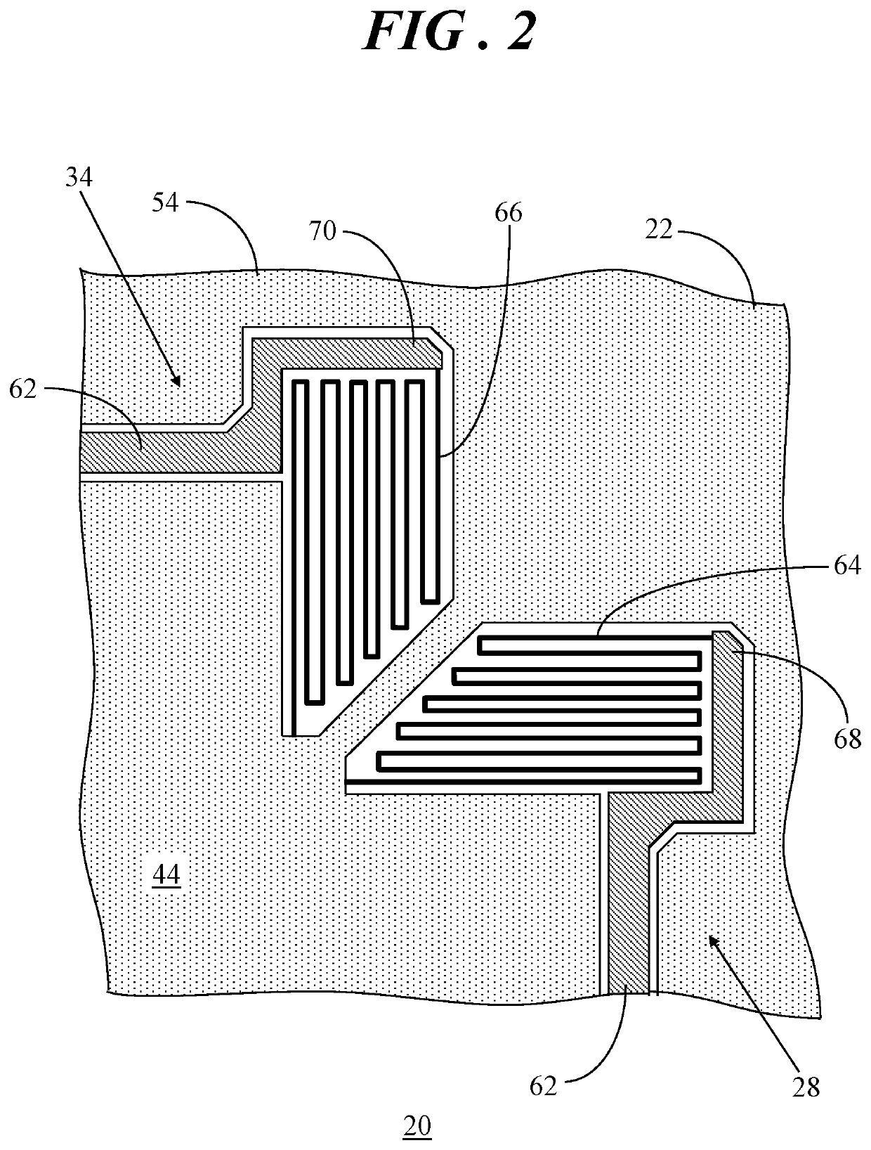
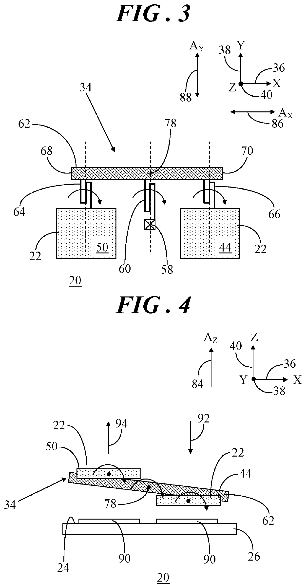
[0010]In overview, the present disclosure concerns microelectromechanical systems (MEMS) inertial sensors with enhanced suppression of parasitic modes, and therefore enhanced sensitivity. More particularly, embodiments entail MEMS accelerometer devices capable of sensing acceleration forces along the Z-axis while suppressing parasitic lateral modes. In general, embodiments described herein provide differential sensing with enhanced sensitivity by the use of multiple lever structures connected to the proof mass that enable translational motion of the proof mass in response to acceleration along the Z-axis while largely limiting motion in the lateral directions along the X- and Y-axes (i.e., the lateral parasitic modes) to effectively enhance sensor sensitivity and thereby reduce noise and increase resistance to electromagnetic interference. Further, a translational motion based approach, as opposed to prior rotational or teeter-totter motion based approaches, can yield improvements i...


PUM


Abstract

A single axis inertial sensor includes a proof mass spaced apart from a surface of a substrate. The proof mass has first, second, third, and fourth sections. The third section diagonally opposes the first section relative to a center point of the proof mass and the fourth section diagonally opposes the second section relative to the center point. A first mass of the first and third sections is greater than a second mass of the second and fourth sections. A first lever structure is connected to the first and second sections, a second lever structure is connected to the second and third sections, a third lever structure is connected to the third and fourth sections, and a fourth lever structure is connected to the fourth and first sections. The lever structures enable translational motion of the proof mass in response to Z-axis linear acceleration forces imposed on the sensor.

Description

TECHNICAL FIELD OF THE INVENTION[0001]The present invention relates generally to inertial sensor devices. More specifically, the present invention relates to a microelectromechanical system (MEMS) inertial sensor device for detecting Z-axis linear acceleration force.BACKGROUND OF THE INVENTION[0002]Microelectromechanical systems (MEMS) technology has achieved wide popularity in recent years, as it provides a way to make very small mechanical structures and integrate these structures with electrical devices on a single substrate using conventional batch semiconductor processing techniques. One common application of MEMS is the design and manufacture of inertial sensor devices (e.g., accelerometers, gyroscopes, and so forth). MEMS inertial sensors are widely used in applications such as automotive, inertial guidance systems, household appliances, game devices, protection systems for a variety of devices, and many other industrial, scientific, and engineering systems.[0003]One type of ...

Claims


Application Information

Patent Timeline
Patent Type & Authority Patents(United States)
IPC IPC(8): G01P15/08G01P15/13G01C19/5656G01P15/18G01P15/125G01C19/5755
CPCG01P15/0802G01P15/13G01C19/5755G01C19/5656G01P15/125G01P15/18G01P2015/0848G01P2015/0837
Inventor TANG, JUNMCNEIL, ANDREW C.KORDESTANI, KAJAL RAHIMIAN
Owner NXP USA INC
Learn More