System and method for dynamically and efficently directing evacuation of a building during an emergency condition

a dynamic and efficient evacuation and emergency technology, applied in the field of emergency response systems, can solve the problems of affecting the evacuation process, the evacuation route may be unknown or inaccessible to an occupant, and the evacuation route may become blocked or unsafe, so as to achieve quick, safe and efficient response.

Inactive Publication Date: 2009-08-25
IBM CORP
View PDF17 Cites 168 Cited by
  • Summary
  • Abstract
  • Description
  • Claims
  • Application Information

AI Technical Summary

Benefits of technology

[0009]In view of the above-described problem, it is an object of the present disclosure to provide a method of directing evacuation of a building during an emergency condition. The method provides a dynamic system which continuously adjusts the supplied optimal evacuation routes in real-time based on the evolution of the emergency condition, flow of evacuees, location of emergency personnel, and changes in the structural integrity of the building. The advantages inherent to such a system provide for a quicker, safer, and more efficient response to emergency conditions.

Problems solved by technology

Such an evacuation route is a necessary safety precaution due to the remote, but ever-present threat of danger.
The danger itself may appear as, for example, a fire, gas leak, or structural collapse.
However, it is possible that an evacuation route may be unknown or inaccessible to an occupant.
It is also possible that the route may become blocked or unsafe due to propagation of an emergency condition.
This, in itself, can become hazardous, particularly if people are in a panicked state.
However, during these situations building occupants do not have the situational awareness, contextual knowledge, or time to properly assess all available options to determine the optimal evacuation route.

Method used


Image

  • System and method for dynamically and efficently directing evacuation of a building during an emergency condition
  • System and method for dynamically and efficently directing evacuation of a building during an emergency condition
  • System and method for dynamically and efficently directing evacuation of a building during an emergency condition

Examples


Embodiment Construction

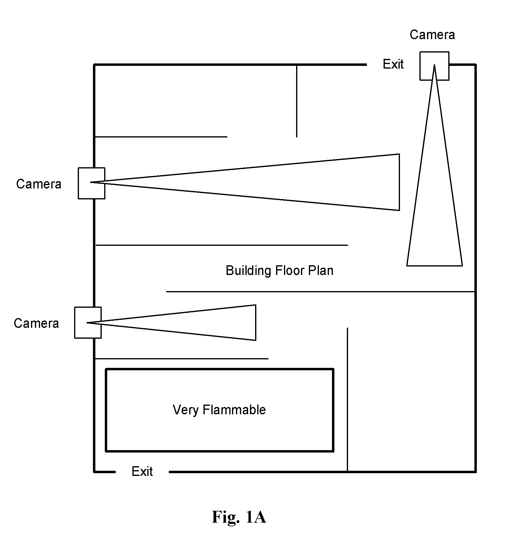
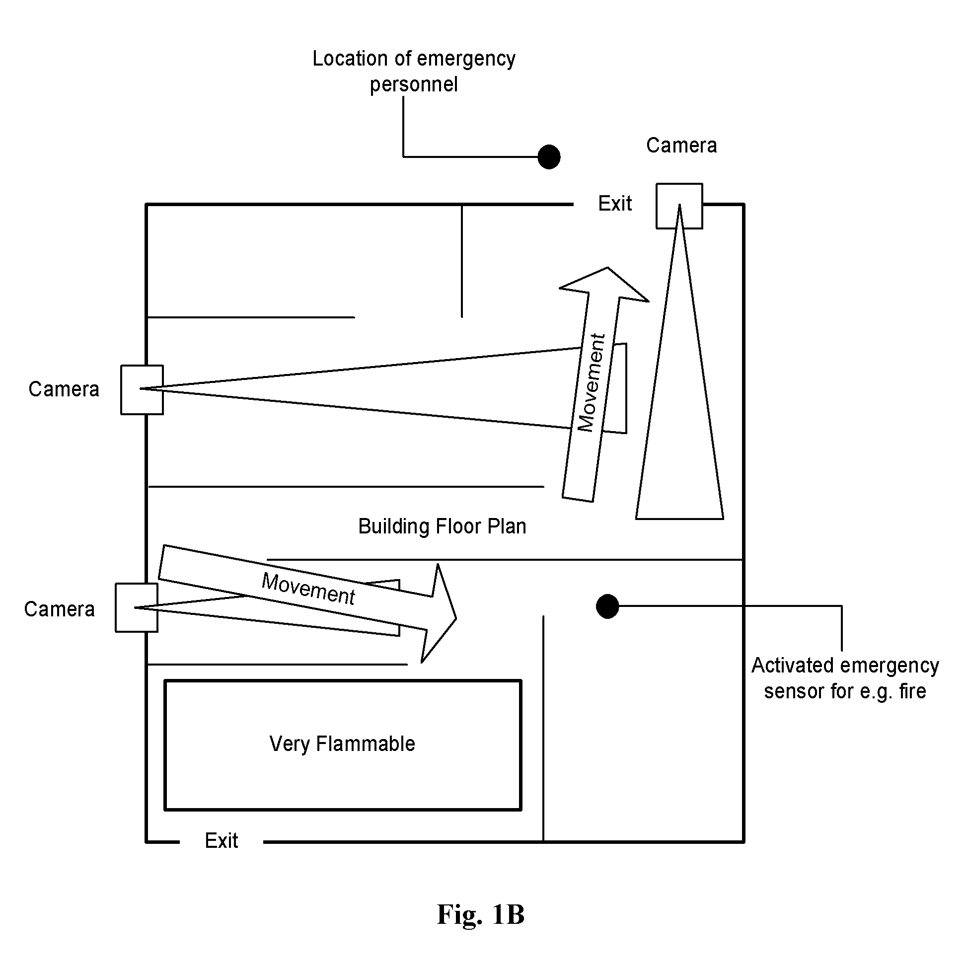
[0015]The above and other objectives of the disclosure will become clearer from the following description and exemplary embodiments which, when taken in conjunction with FIGS. 1A-B, explain the disclosure in greater detail.

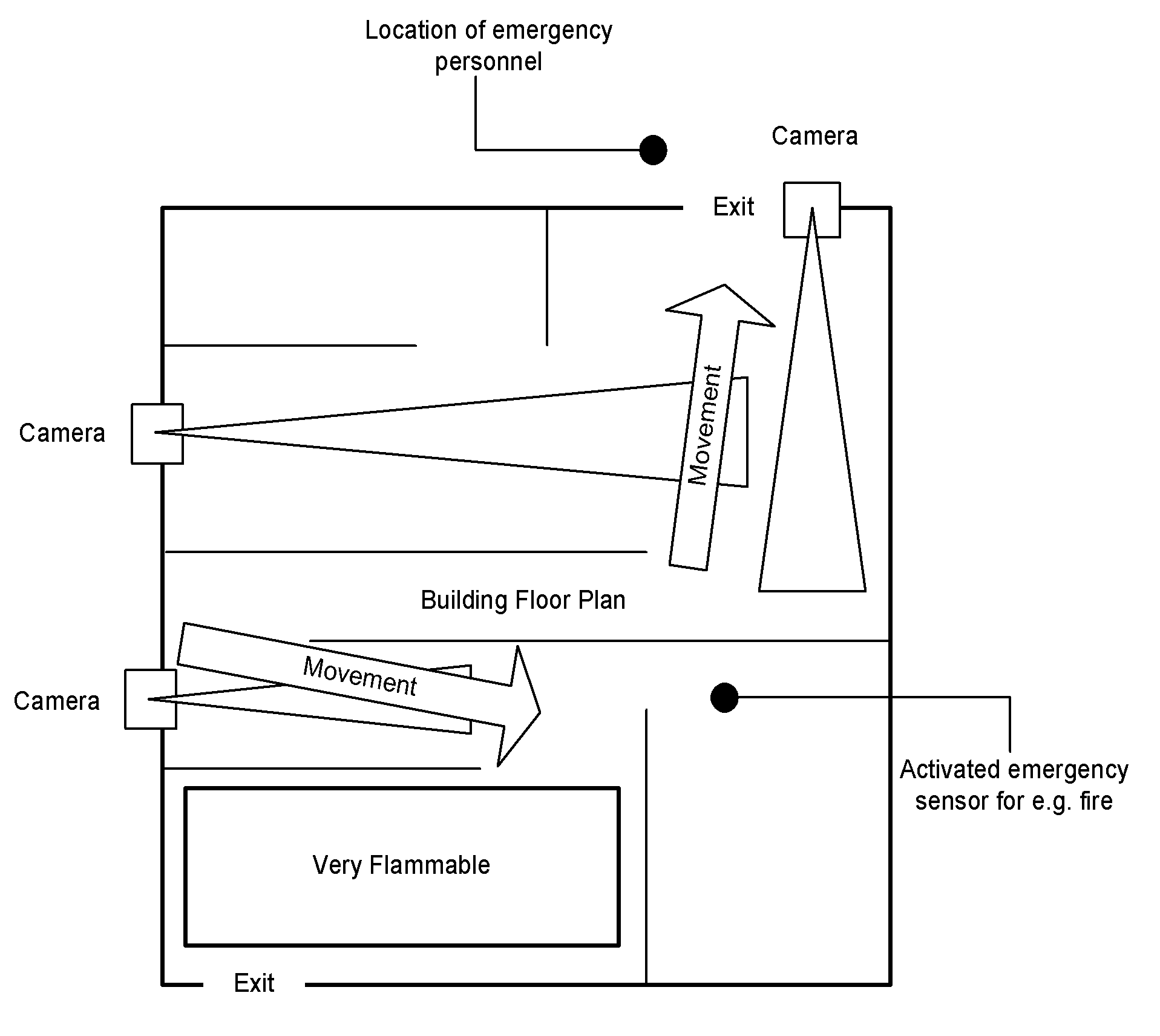
[0016]The disclosure is directed to an emergency response system which calculates a plurality of evacuation routes in real-time using situation-aware data in conjunction with information about the context of the situation. Situational awareness involves the use of decentralized data (i.e., video feed from different cameras, voice recognition from microphones) to determine, for example, the flow of evacuees toward a certain exit and then redirect a plurality of them to alternative exits based upon a real-time analysis of the video feed. Such an analysis may be done automatically using the appropriate software capable of recognizing and analyzing video and audio content. By redirecting some of the evacuees along alternate evacuation routes problems due to congestion...


PUM


Abstract

An emergency response system capable of directing building occupants to a safe location in real-time is disclosed. The system comprises a plurality of sensors which detect and monitor an emergency condition, a central processing unit which evaluates the data, calculates accessible evacuation routes, and sends the result to output devices which provide directional information to occupants. By combining an analysis of the flow of evacuees with changes in building structural information and the evolution of an emergency condition the system combines situation-aware data with contextual information to thereby provide the best available evacuation route to evacuees. In this manner, some evacuees may be redirected to alternate evacuation routes during the evacuation process itself, thereby minimizing problems due to congestion, potential panic of the evacuees, and changes in the emergency condition while increasing the probability that evacuees will reach a safe location.

Description

BACKGROUND[0001]1. Field of the Disclosure[0002]This disclosure relates generally to an emergency response system. In particular, the present disclosure relates to a method of directing evacuation of a building by combining situation-aware data with knowledge about the context of an emergency condition.[0003]2. Description of the Related Art[0004]Any type of building or structural enclosure capable of holding a number of people at any given time is generally required to have at least one evacuation route available to occupants. Such an evacuation route is a necessary safety precaution due to the remote, but ever-present threat of danger. The danger itself may appear as, for example, a fire, gas leak, or structural collapse. Environmental factors such as a hurricane, tornado, or earthquake may also create an emergency condition. Whatever the cause, in each instance it is necessary for the building to have a means of directing occupants to either exit the building via the appropriate ...

Claims


Application Information

Patent Timeline
Patent Type & Authority Patents(United States)
IPC IPC(8): G08B29/00
CPCG08B7/066G08B25/14
Inventor RICHTER, CHRISTIANSANSO, ANTONIOROCKETT, DAVIDNERSU, HARSHITA
Owner IBM CORP
Why Eureka
Try Eureka