
Wireless LAN communication system, wireless LAN connection method, and wireless LAN terminal apparatus

a technology of wireless lan and communication system, applied in the direction of power management, wireless commuication services, high-level techniques, etc., can solve the problem of useless power consumption, achieve the effect of reducing power consumption, reducing scanning operations, and reducing power consumption

Active Publication Date: 2009-08-25
LENOVO INNOVATIONS LTD HONG KONG
View PDF14 Cites 41 Cited by
  • Summary
  • Abstract
  • Description
  • Claims
  • Application Information

AI Technical Summary

Benefits of technology

The present invention provides a wireless LAN communication system and a wireless LAN connection method that can reduce power consumption during the automatic homing operation performed between a base station apparatus and a wireless LAN terminal apparatus. This is achieved by lengthening the scan pause time period, which is the time between previous scanning operations, when the wireless LAN terminal apparatus searches the base station apparatus of a connection destination. This allows for a gradual reduction in power consumption when there is no base station apparatus to be connected. Additionally, the wireless LAN terminal apparatus can set multiple base station apparatuses with priority to select the most suitable base station apparatus for connection, further minimizing power consumption and scanning operations.

Problems solved by technology

In the conventional wireless LAN communication systems described above, even when there is no AP around the wireless LAN terminal apparatus, an active scan is repeated at a given interval at the time of the automatic homing operation, thus resulting in useless power consumption.

Method used


Image

  • Wireless LAN communication system, wireless LAN connection method, and wireless LAN terminal apparatus
  • Wireless LAN communication system, wireless LAN connection method, and wireless LAN terminal apparatus
  • Wireless LAN communication system, wireless LAN connection method, and wireless LAN terminal apparatus

Examples


Embodiment Construction

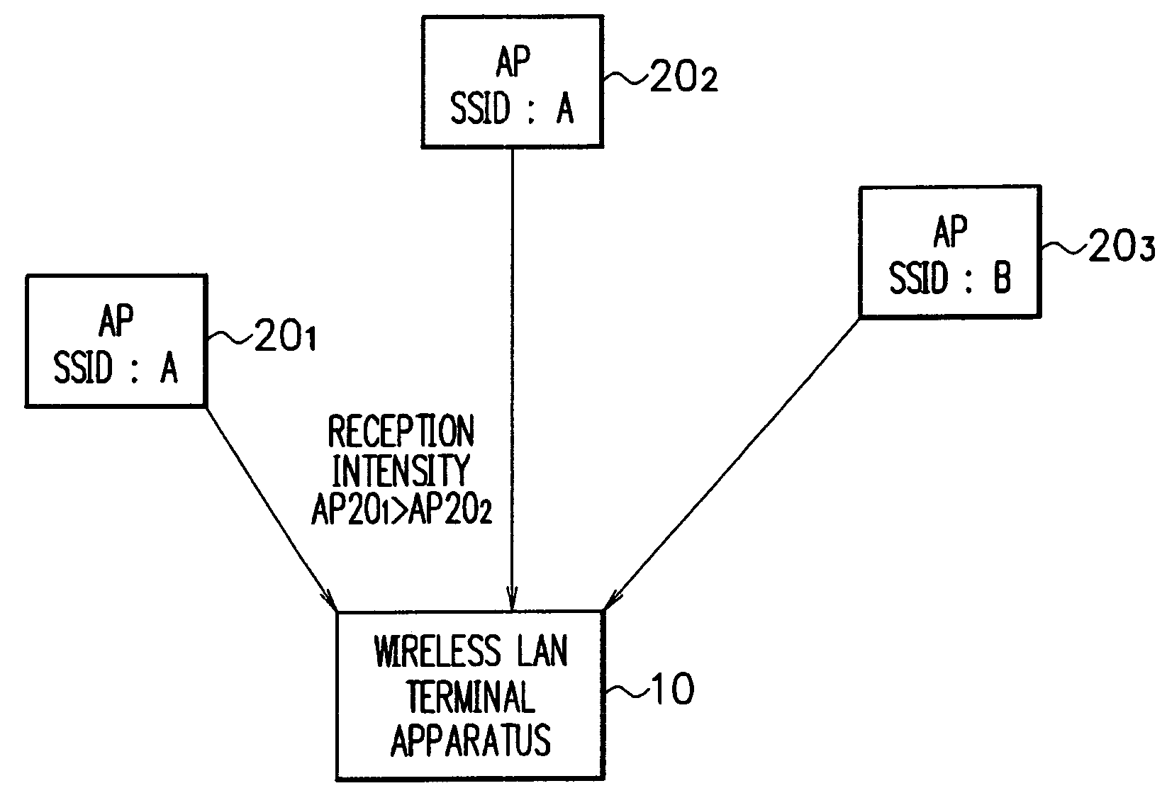
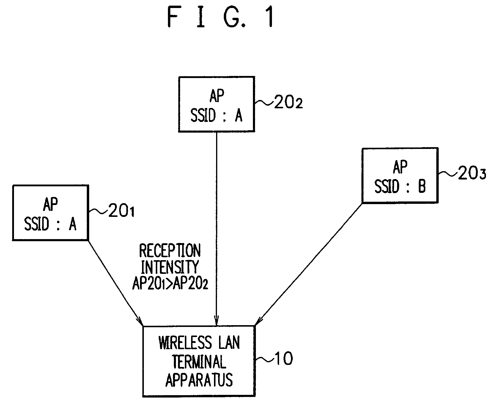
[0024]An embodiment of the present invention will now be described in detail with reference to the accompanying drawings. FIG. 1 is a block diagram showing a configuration of a wireless LAN communication system according to an embodiment of the present invention.

[0025]The wireless LAN communication system of the present embodiment shown in FIG. 1 includes a wireless LAN terminal apparatus 10 and three base station apparatuses (AP) 201 to 203.

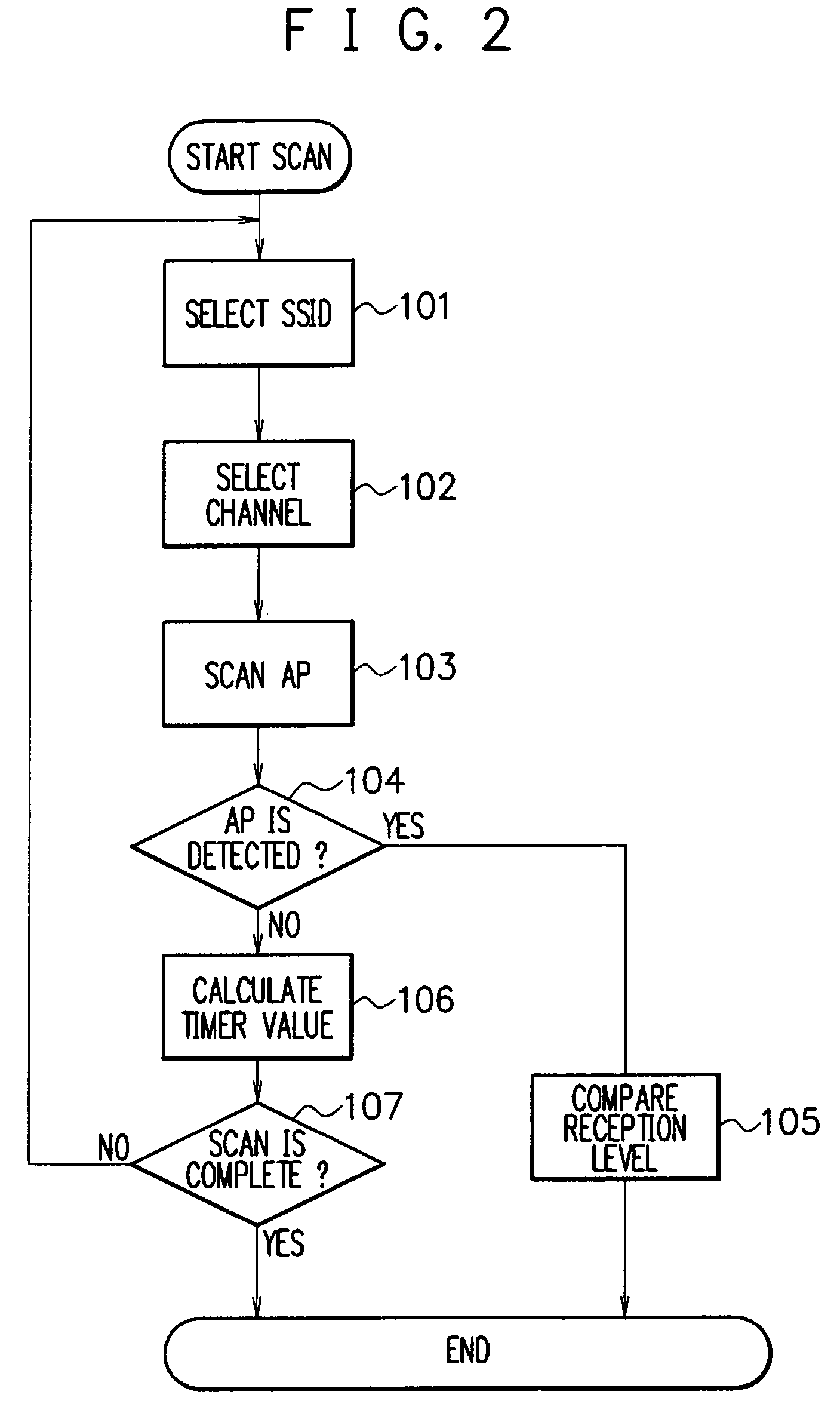
[0026]When an automatic homing operation is performed in which scanning operation is repeated for searching a connection destination AP, the wireless LAN terminal apparatus 10 does not leave unchanged a scan pause time period which is a period of time from the previous scanning operation to the next scanning operation, but lengthens the scan pause time period as the number of scanning operations increases. More specifically, each time the scanning operation is repeated predetermined number n times, the wireless LAN terminal apparatus extends the...


PUM


Abstract

An object of the invention is to reduce the power consumption at the time of an automatic homing operation performed between a base station apparatus and a wireless LAN terminal apparatus. When an automatic homing operation is performed in which a scanning operation is repeated for searching an AP as a connection destination, the wireless LAN terminal apparatus 10 does not leave unchanged a scan pause time period which is a period of time between the previous scanning operation to the next scanning operation, but lengthens it as the number of scanning operations increases. More specifically, each time the scanning operation is repeated predetermined number n times, the wireless LAN terminal apparatus extends the scan pause time period by a given incremental value. The wireless LAN terminal apparatus has an upper limit value of the scan pause time period preliminarily set therein. Thus the scan pause time period is made not to exceed the upper limit value.

Description

BACKGROUND OF THE INVENTION[0001]1. Field of the Invention[0002]The present invention relates to a wireless LAN communication system including a wireless LAN terminal apparatus having a wireless LAN (IEEE802. 11a / 11g / 11b) connection function and a base station apparatus making a wireless connection to the wireless LAN terminal apparatus to connect the terminal apparatus to the network, and more particularly to a wireless LAN connection method for establishing a connection between the wireless LAN terminal apparatus and the base station apparatus.[0003]2. Description of Related Art[0004]In recent years, hot spot services are attracting great attention which provides Internet-access by use of wireless LAN in a specific shop or the like. In addition, wireless LAN requiring no connection cable is also widely diffusing into households.[0005]In such a wireless LAN communication system, in order to connect with the wireless LAN network, firstly the wireless LAN terminal apparatus has to se...

Claims


Application Information

Patent Timeline
Patent Type & Authority Patents(United States)
IPC IPC(8): H04W4/00H04L12/28H04W48/16H04W48/20H04W52/02H04W84/12H04W88/08
CPCH04W48/20Y02B60/50H04W52/0245H04W84/12Y02D30/70
Inventor ARAIYAMAZAKI, HITOSHIITOU, MASASHI
Owner LENOVO INNOVATIONS LTD HONG KONG
Learn More