Diagnostic system for a power machine

a technology for power machines and diagnostic systems, applied in the direction of process and machine control, testing/monitoring control systems, instruments, etc., can solve the problem of burdensome review and analysis of a large volume of sensor data

Inactive Publication Date: 2009-08-25
CLARK EQUIP CO INC
View PDF12 Cites 27 Cited by
  • Summary
  • Abstract
  • Description
  • Claims
  • Application Information

AI Technical Summary

Problems solved by technology

Review and analysis of a large volume of sensor data can be burdensome.

Method used


Image

  • Diagnostic system for a power machine
  • Diagnostic system for a power machine
  • Diagnostic system for a power machine

Examples


Embodiment Construction

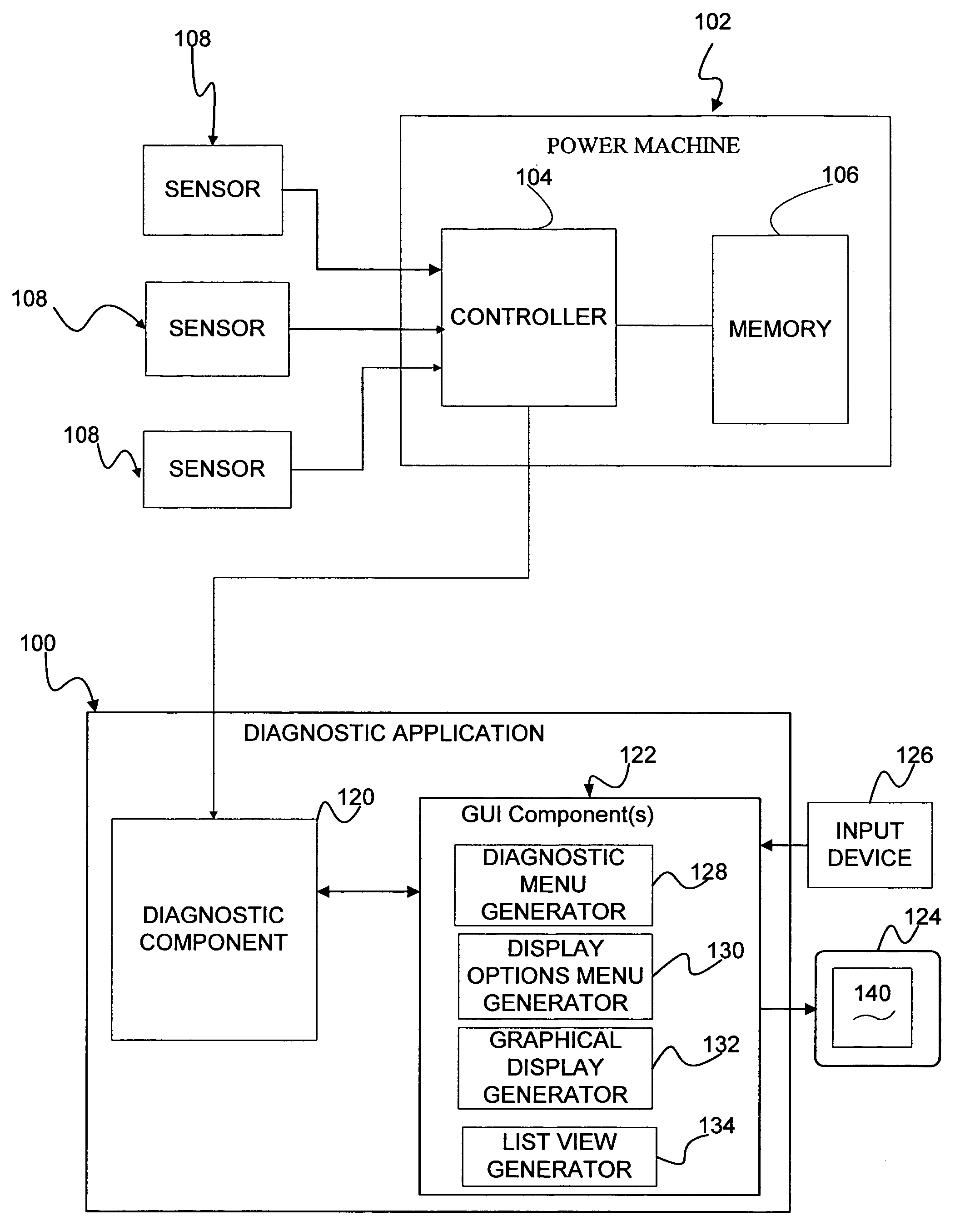
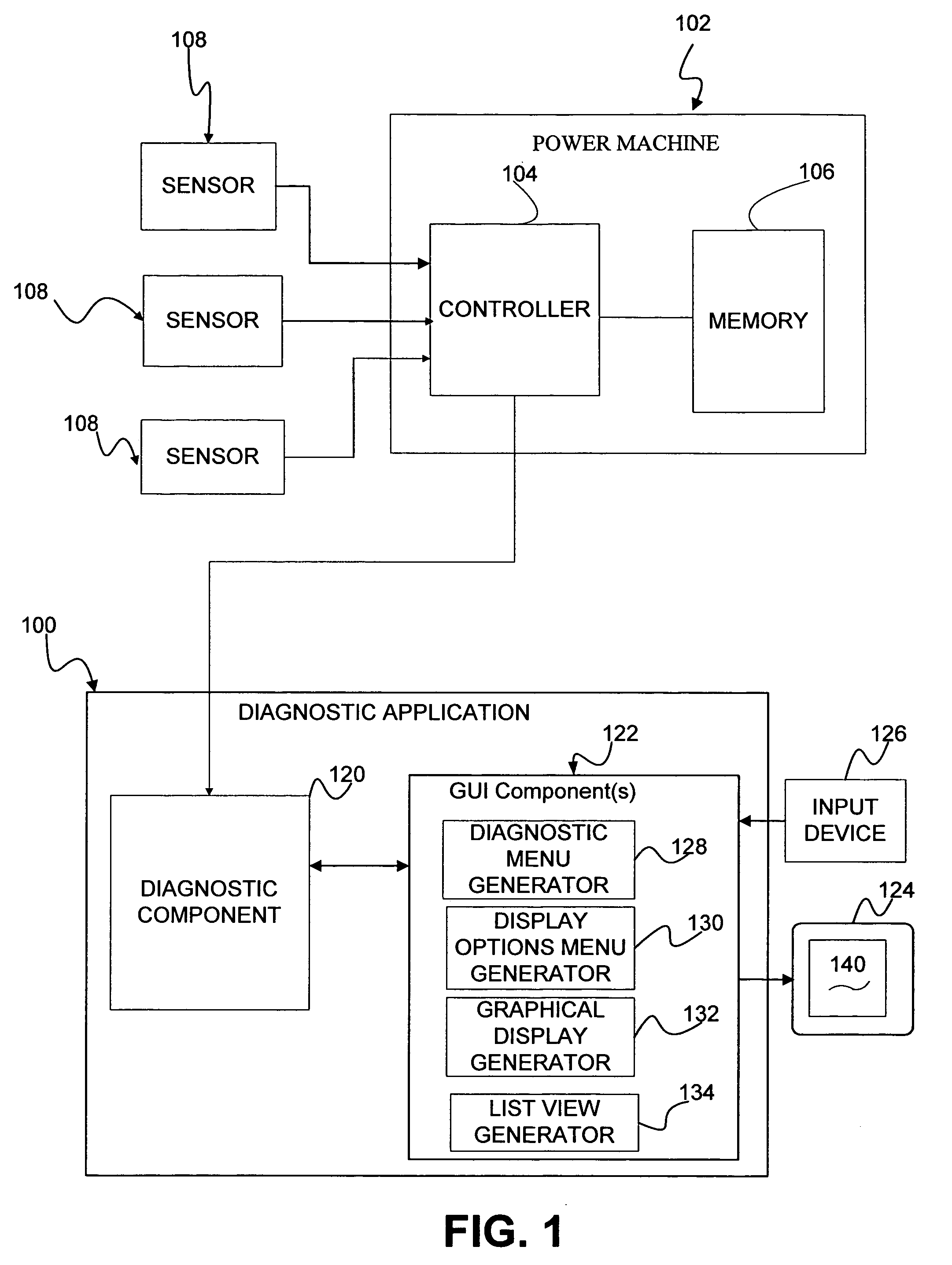
[0012]The present application relates to a diagnostic application 100 that can be implemented on a personal computer, hand held computer or other programming device, for use in association with a power machine or vehicle 102 illustrated diagrammatically in FIG. 1. As shown in FIG. 1, power machine 102 includes a controller 104, memory 106 and one or more sensors 108 to monitor system parameters. Controller 108 is illustratively a digital computer, microprocessor or microcontroller and memory 106 can be integrated with controller 106 or provided separately. Sensors 108 can include temperature, pressure or other “on-board” or “off-board” sensors to monitor engine temperature, oil pressure or temperature, hydraulic oil charge pressure or other diagnostic parameters.

[0013]The diagnostic application 100 is configured to retrieve, manipulate and display data from the sensors 108. As shown, the diagnostic application 100 includes a diagnostic component 120 and a graphical user interface co...


PUM


Abstract

A diagnostic application or system for a power machine is disclosed. The diagnostic application or system generates a diagnostic menu to select one or more diagnostic items for diagnostic monitoring. Sensor data for the selected items is retrieved from one or more sensors and displayed on an electronic display device. In the embodiments described, the application or system includes a graphical user interface component configured to generate a display options menu including one or more user selectable display formats or options.

Description

BACKGROUND OF THE INVENTION[0001]Power machines or vehicles typically have sensors which provide readings or data for different operating parameters of the machine or vehicle. For example, power machines, such as a skid steer loader, typically have temperature and pressure sensors to monitor hydraulic oil pressures and temperatures, engine coolant temperatures and other system parameters. Feedback or data from sensors can be outputted to a screen or display to warn of a potential problem or used for diagnostic evaluation. Sensor data allows a technician to view operating performance over a period of time and under different operating conditions. Review and analysis of a large volume of sensor data can be burdensome.SUMMARY OF THE INVENTION[0002]The present invention relates to a diagnostic application or system for a power machine. The application or system includes a menu generator that is configured to generate a diagnostic menu including one or more user selectable diagnostic ite...

Claims


Application Information

Patent Timeline
Patent Type & Authority Patents(United States)
IPC IPC(8): G06F19/00
CPCG05B23/0267G07C3/00G07C5/0825G07C5/0808G07C2205/02
Inventor MINDEMAN, SPENCER L.
Owner CLARK EQUIP CO INC
Why Eureka
Try Eureka