Bone fixing device

a bone fixing and bone technology, applied in the field of bone fixing devices, can solve the problems of steel cable carving into the bone, risk of stitching and possible blood contact, and the difficulty of fixing by knots, clamps or other means, and achieve the effect of improving the stability and stability of the bone fixing devi

Inactive Publication Date: 2009-09-01
DSM IP ASSETS BV
View PDF10 Cites 7 Cited by
  • Summary
  • Abstract
  • Description
  • Claims
  • Application Information

AI Technical Summary

Benefits of technology

[0028]In a preferred embodiment of this method a bar is inserted between the fixing plates before the cable is tensioned and is removed after the cable has been tensioned. This embodiment has the advantage that the clamping force only works after the bar has been removed and is not hampering the tensioning of the cable before. The thickness of the bar can be small but to have the full benefit of its presence it is preferably at least equal to the thickness of the cable. Since the removal of the bar may lead to a minimal elongation of the tensioned part of the cable the bar should be thin, preferably no more than 10 and more preferably no more than 5 or even 2 mm.

Problems solved by technology

They are prone to fatigue leading to breakage of the composing steel fibers after which the sharp ends stick out into the body.
Breakage of the fibers during their application by a surgeon brings the risk of stitching and possible blood contact.
Further, steel is a hard material and being tensioned around the bone there is the risk of carving of the steel cable into the bone.
Fibers of this type, however, are notorious for their difficulty to be fixed by knots, clamps or other means when they are under tension.
It should be noted that in constructions of these fibers, e.g. in braids and twisted bundles an efficiency loss occurs, i.e. that the resulting strength of the construction is lower that then the sum of the strengths of the constituting fibers.
These tensioning devices can be connected to the cable in such a way that only a drawing force is exerted on the cable, resulting in its shortening and tensioning but also in such a way that, instead of or next to the drawing force, also a twisting force is exerted the cable, also resulting in further tensioning the cable.

Method used


Image

  • Bone fixing device
  • Bone fixing device
  • Bone fixing device

Examples


Embodiment Construction

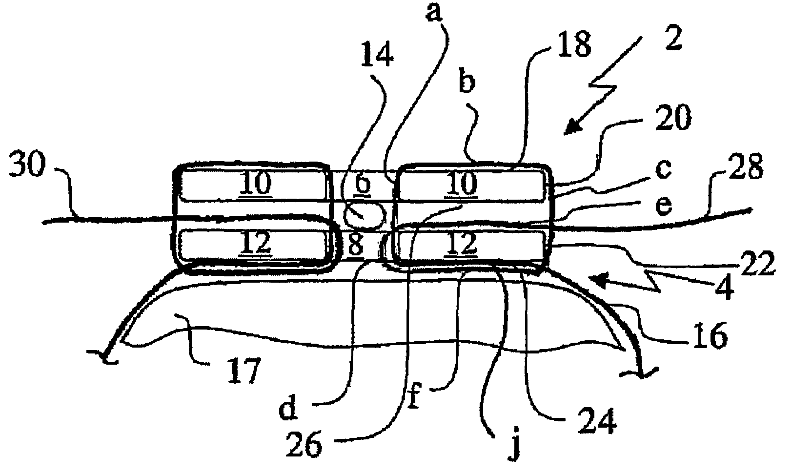
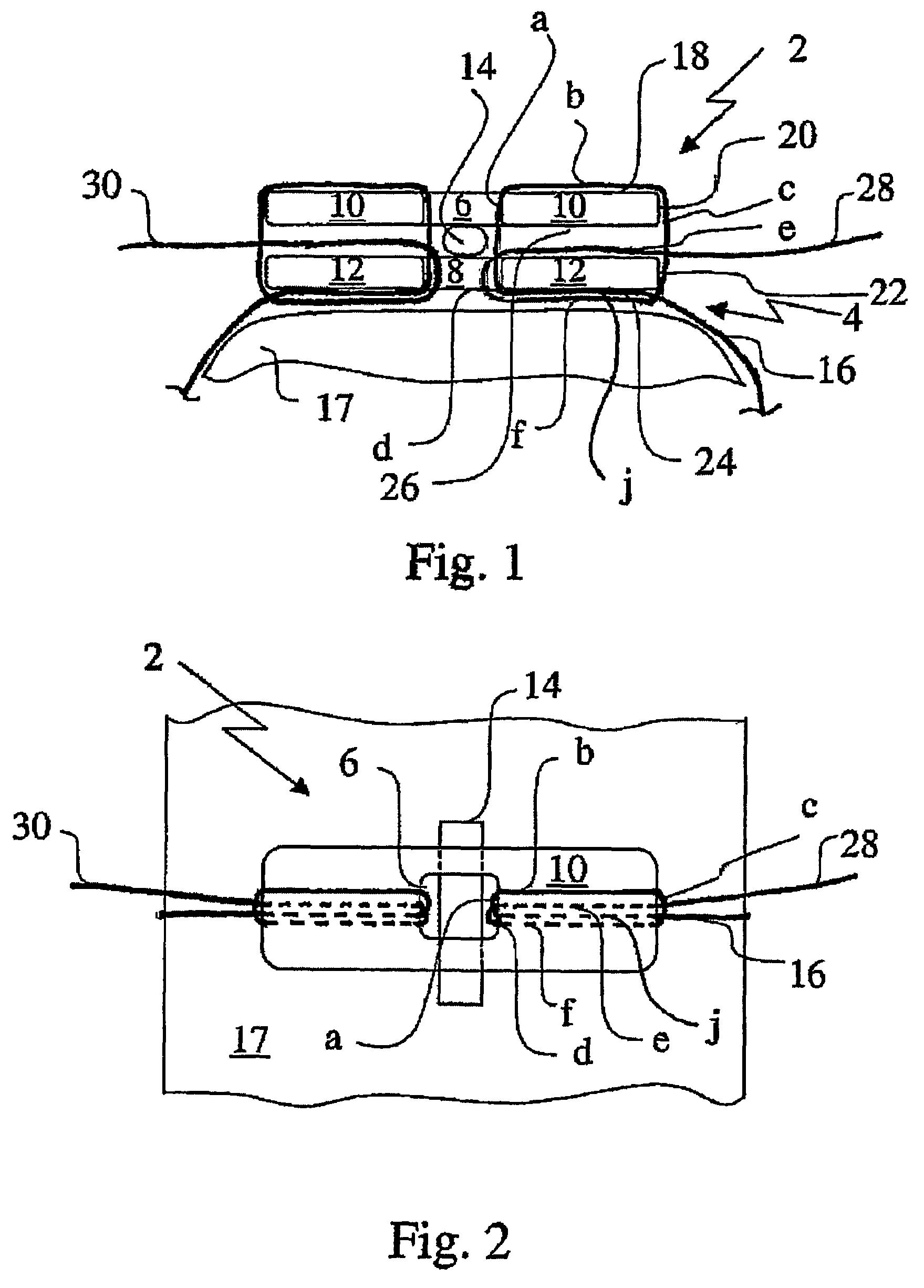
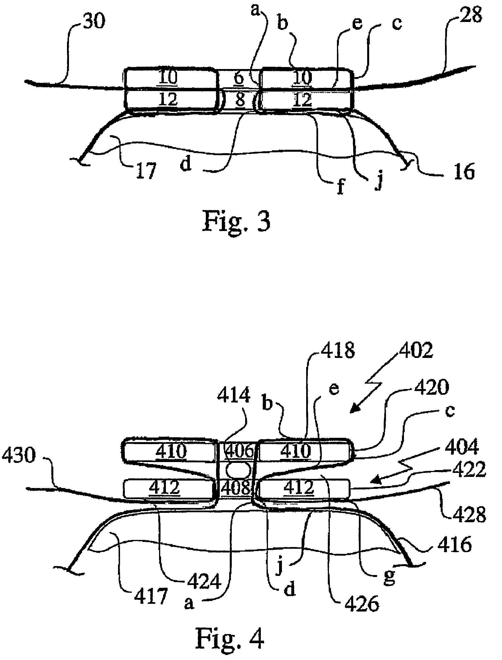
[0039]In FIG. 1 the numbers 2 and 4 denote round fixing plates having a hole 6 resp. 8 surrounded by a ring 10 resp. 12. Between the fixing plates a removable bar 14 is present, Cable 16 surrounds bone parts 17 (not fully shown). One end of cable 16 runs along the trajectory in which parts (a) to (f) are distinguished. Herein part (a) runs upward from below through the holes 8 and 6, then bends to the right in an outward direction and runs as part (b) along the upper surface 18 of the ring 10 to the outer edge thereof, where it bends downward to run as part (c) along the outer circumference 20 and 22 of the rings 10 and 12. The cable then bends to the left in an inward direction and runs as part (f) along the lower surface 24 of ring 12 to the inner edge of this ring, where it bends upward to run as part (d) through hole 8 in plate 4. Finally the cable runs as part (e) through the gap 26 in outward direction bringing end 28 out of the gap. The other end of cable 16 follows a similar...


PUM


Abstract

Bone fixing devices include (I) a surgical cable having a first end and a second end and (II) at least a first fixing plate and a second fixing plate. The first and second fixing plates are respectively provided with first and second central holes and first and second rings surrounding the first and second holes. The circumference of each fixing plate defines an outer edge of its respective ring and an inner edge of the ring being adjacent to the hole it surrounds. The first fixing plate is in a stacked position on top of the second plate so as to define a gap therebetween with the plates and the holes at least partly overlapping each other. The cable ends follow a continuous trajectory running around and between the plates and through the holes in such way that by drawing the cable ends the cable is tensioned around the bone parts so as to and fixate the same.

Description

[0001]This application is the US national phase of international application PCT / NL2004 / 000086 filed 6 Feb. 2004 which designated the U.S. and claims benefit of EP 03075381.8, dated 7 Feb. 2003 and U.S. 60 / 445,464, dated 7 Feb. 2003, the entire content of which is hereby incorporated by reference.FIELD OF INVENTION[0002]The invention relates to a method for fixing bone parts by means of a Surgical cable.BACKGROUND AND SUMMARY OF THE INVENTION[0003]In modern surgery on many occasions there is a need for immobilizing bone parts that have been separated in the course of an operation and have to grow together again or to keep a bone part at a fixed and constant distance and position with respect to another bone part or an orthopedic device such as a splint, further denoted as fixing bone parts. Also in the treatment of bone fractures this need for fixing bone parts that came apart is required for at least the time needed to have the body repair the fracture or for longer times, in many ...

Claims


Application Information

Patent Timeline
Patent Type & Authority Patents(United States)
IPC IPC(8): A61B17/82A61B17/04A61B17/84
CPCA61B17/823A61B17/8869A61B17/842A61B17/0487A61B2017/0459
Inventor MARISSEN, ROELOFWETZELS, KAREL JOZEF
Owner DSM IP ASSETS BV
Why Eureka
Try Eureka