PWM signal generating circuit

a signal generation circuit and signal technology, applied in the direction of pulse generation by vacuum tubes, pulse techniques, instruments, etc., can solve the problems of increasing the cost of circuit configuration, and high cost of comparator with low drift and low offs

Inactive Publication Date: 2009-09-01
TOYOTA JIDOSHA KK
View PDF15 Cites 6 Cited by
  • Summary
  • Abstract
  • Description
  • Claims
  • Application Information

AI Technical Summary

Benefits of technology

[0016]According to the first or the second aspect of the invention, it is possible to provide the PWM signal generating circuit that is able to generate the high-resolution PWM signal without using a high-speed clock.

Problems solved by technology

This increases the cost of the circuit configuration.
In addition, a comparator with low drift and low offset is usually expensive.
This increases the cost of the circuit configuration, as with the digital PWM signal generating circuit.
However, the resolution of the PWM signal is not uniformly increased with the art described above.

Method used


Image

  • PWM signal generating circuit
  • PWM signal generating circuit
  • PWM signal generating circuit

Examples


Embodiment Construction

[0024]Hereafter, embodiments of the invention will be described in detail with reference to accompanying drawings.

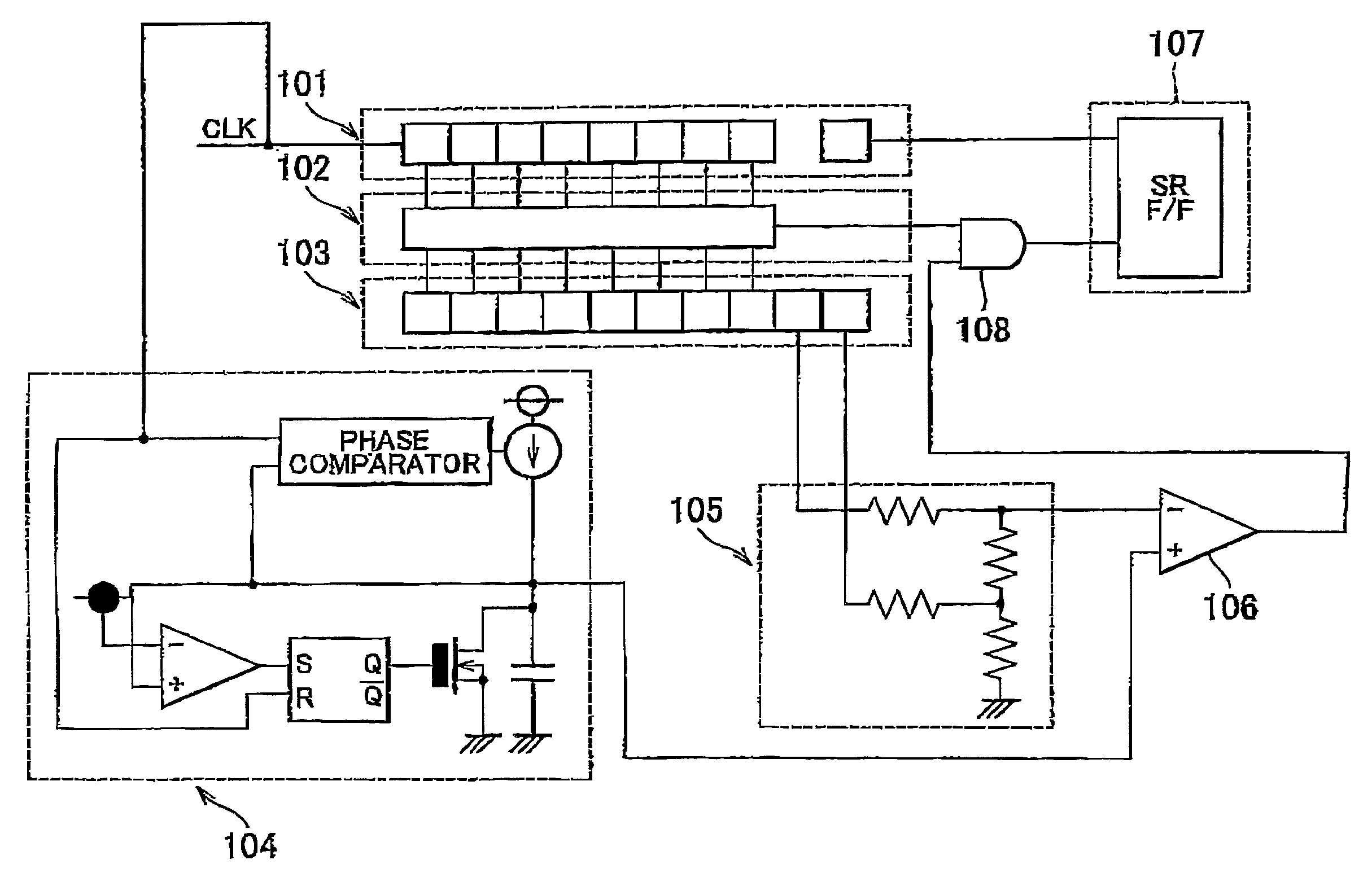
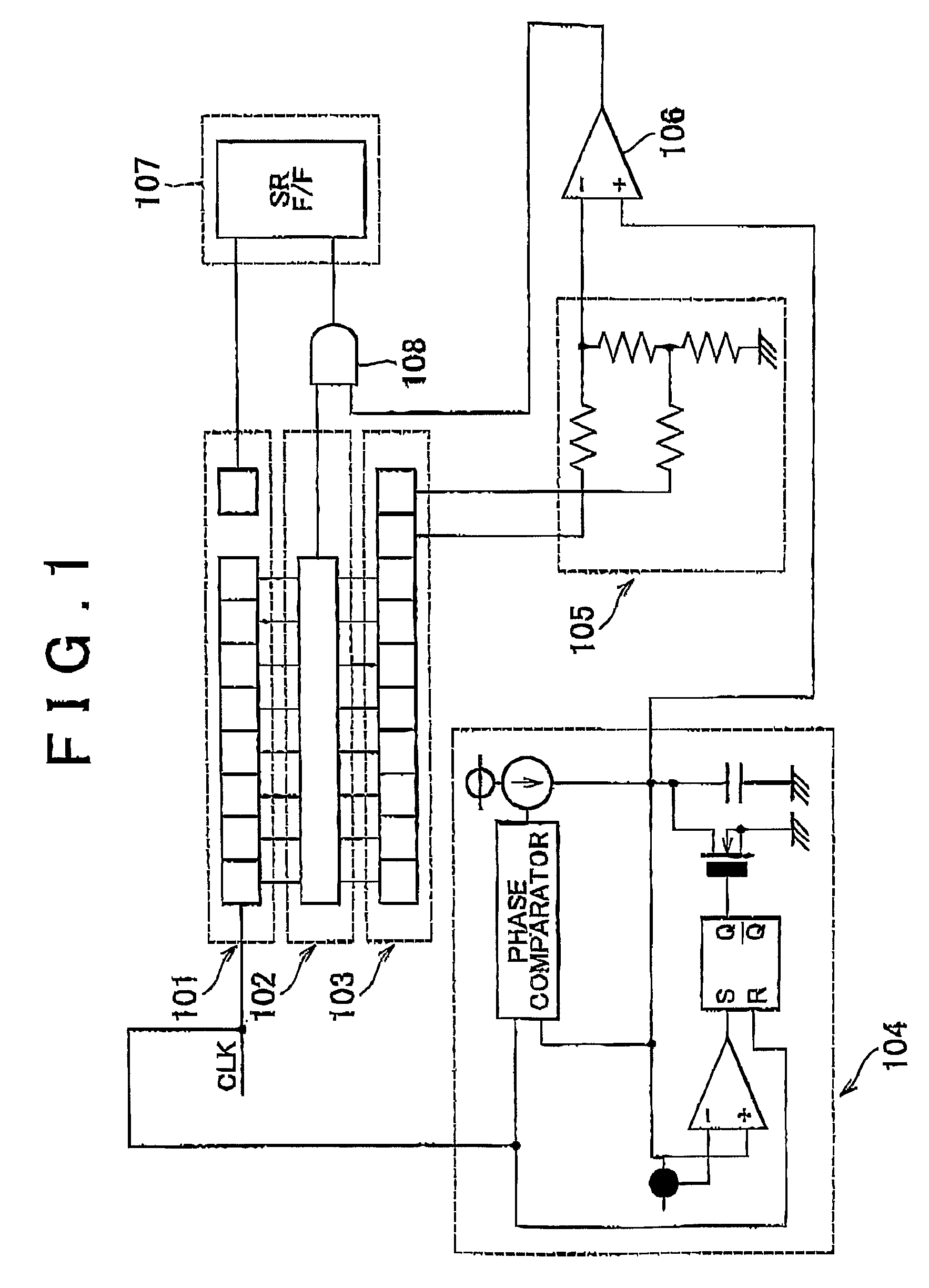
[0025]First, a PWM signal generating circuit according to the invention will be described with reference to FIG 1. FIG. 1 shows a counter 101, a comparator 102, a duty ratio setting registor 103, a ramp wave generator 104, a D / A converter 105, a comparator 106, a flip-flop 107, and an AND circuit 108.

[0026]The counter 101 is incremented on each leading or trailing edge of a clock signal CLK. When the counter 101 overflows, a signal indicating “H” is output. In the example shown in the figure, the counter 101 is an 8-bit up-counter.

[0027]The comparator 102 compares an output from the duty ratio setting register 103 with an output from the counter 101. If the output from the duty ratio setting register 103 matches the output from the counter 101, the comparator 102 outputs a signal indicating “H”. In the example shown in the figure, the duty ratio setting register 103 stor...


PUM


Abstract

A PWM signal generating circuit according to the invention includes a digital PWM signal generating circuit that generates a digital PWM signal having a resolution of 2n based on a clock signal CLK and n-bits (n≧1) of digital information; a triangular wave generator that generates a triangular wave (e.g. ramp wave) synchronized with the clock signal CLK; and a comparator that compares the triangular wave with a threshold value. The PWM signal generating circuit increases the resolution of the digital PWM signal based on an output from the comparator.

Description

BACKGROUND OF THE INVENTION[0001]1. Field of the Invention[0002]The invention relates to a PWM signal generating circuit that is able to generate a high-resolution PWM signal without using a high-speed clock.[0003]2. Description of the Related Art[0004]A PWM wave generating circuit that controls an output voltage is described in, for example, Japanese Patent Application Publication No. JP-A-2001-169541. The PWM wave generating circuit described in this publication includes a constant current circuit in which a current value changes based on a feedback voltage; a capacitor that is charged with electric currents from the constant current circuit; a switch circuit that releases an electric charge of the capacitor; an A / D (analog-to-digital) converter that receives the feedback voltage and transmits a digital signal to a delay circuit; the delay circuit that receives the digital signal and controls the switch circuit; and a first comparator that controls a voltage of a PWM wave using th...

Claims


Application Information

Patent Timeline
Patent Type & Authority Patents(United States)
IPC IPC(8): H03K7/08H03B19/00H03K3/04
CPCH03K7/08
Inventor MAKITA, MITSUGUOJIMA, YOSHITAKAKUME, YOSHINOBU
Owner TOYOTA JIDOSHA KK
Why Eureka
Try Eureka