Geometric measurement system and method of measuring a geometric characteristic of an object

a geometric characteristic and measurement system technology, applied in the field of measurement, can solve the problems of difficult application to highly curved surfaces and/or optically transmissive surfaces, difficult to project light onto the entire surface, and the degree to which the surface can depart from spherical is limited by the dynamic range of the measurement instrumen

Active Publication Date: 2009-09-01
AMO DEVMENT
View PDF23 Cites 20 Cited by
  • Summary
  • Abstract
  • Description
  • Claims
  • Application Information

AI Technical Summary

Benefits of technology

[0009]Neal et al. U.S. Pat. No. 6,184,974 (“Neal et al.”), which is incorporated herein by reference in its entirety as if fully set forth herein, discloses a means for making measurements of a small area of at least one surface of a silicon wafer or other flat surface and for stitching these measurements together to form a measurement of the entire surface. Neal et al. uses overlap regions to connect the measurements together and eliminate any effects of instrument inaccuracy during the measurement process. This same technique has been applied to the measurement of large telescope mirrors with excellent success (Kiikka et al, “The JWST Infrared Scanning Shack Hartmann System: a new in-process way to measure large mirrors during optical fabrication at Tinsley,” SPIE 2006).
[0010]It would be desirable to provide a method and system for measuring one or more geometric characteristics of an object having one or more highly curved, potentially aspheric and non-symmetric surfaces. It would also be desirable to provide a method and system for measuring one or more geometric characteristics of an object that has at least one substantially transparent surface, which can accurately distinguish between first and second surface reflections and provide accurate surface shape maps for each surface.

Problems solved by technology

However, many of these techniques are difficult to apply to highly curved surfaces and / or optically transmissive surfaces.
When objects such as, but not limited to, a contact lens, contact lens mold, high numerical aperture optical element, pin, optical lens, inter-ocular lens (IOL), IOL mold, curved mirror, cornea, or another object with a rapid variation in surface contour is measured, it is very difficult to project the light onto the entire surface and to collect it back in a controlled and uniform fashion.
Furthermore, while good results may be achieved with some of these methods by projecting and then collecting the light from a spherical surface, the degree to which the surface can depart from spherical is limited by the dynamic range of the measurement instrument.
This severely limits the range of objects whose surfaces can be measured since many objects are not spherical but may be highly aspherical.
The light reflected from various surfaces mixes together and makes interpretation of resulting patterns difficult.
While it is possible in some cases to spoil the reflection (or otherwise identify it) from the back surface (or other feature that is not of interest) by painting it black, immersing it in a fluid, or otherwise altering it, this has the effect of damaging the part that is being measured.
This is not generally desirable in a measurement system.
However, it is generally not possible to measure two surfaces simultaneously with a profilometer, and the fact that there is a contact with the surface may damage the object.
In addition, these instruments are very slow and may have different precision on rough surfaces than they do for smooth surfaces.

Method used


Image

  • Geometric measurement system and method of measuring a geometric characteristic of an object
  • Geometric measurement system and method of measuring a geometric characteristic of an object
  • Geometric measurement system and method of measuring a geometric characteristic of an object

Examples


Embodiment Construction

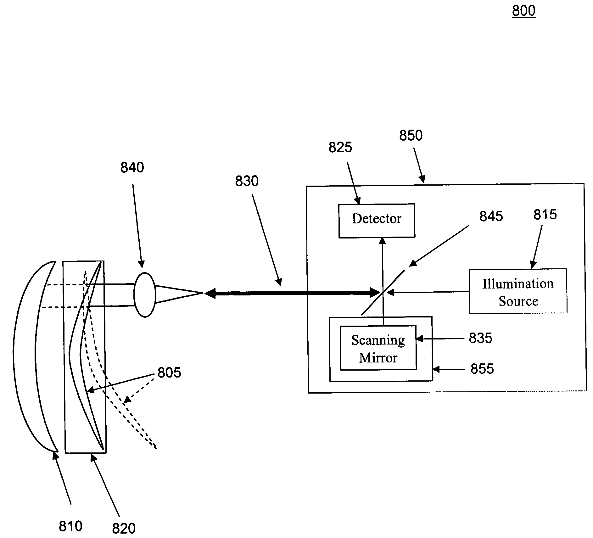
[0029]As discussed above, it is desirable to characterize one or both surfaces of an optically transparent object, or an object having at least one substantially transparent surface, however, in general it is difficult to separate the reflection from the front surface from that of the back surface. However, in the case of a highly curved surface, such as is typical of a contact lens, contact lens mold, aspheric optic, IOL, cornea or other highly curved object, we disclose below systems and methods for separating the two surfaces in order isolate the surfaces for measurement and / or to measure the two surfaces (either sequentially or simultaneously).

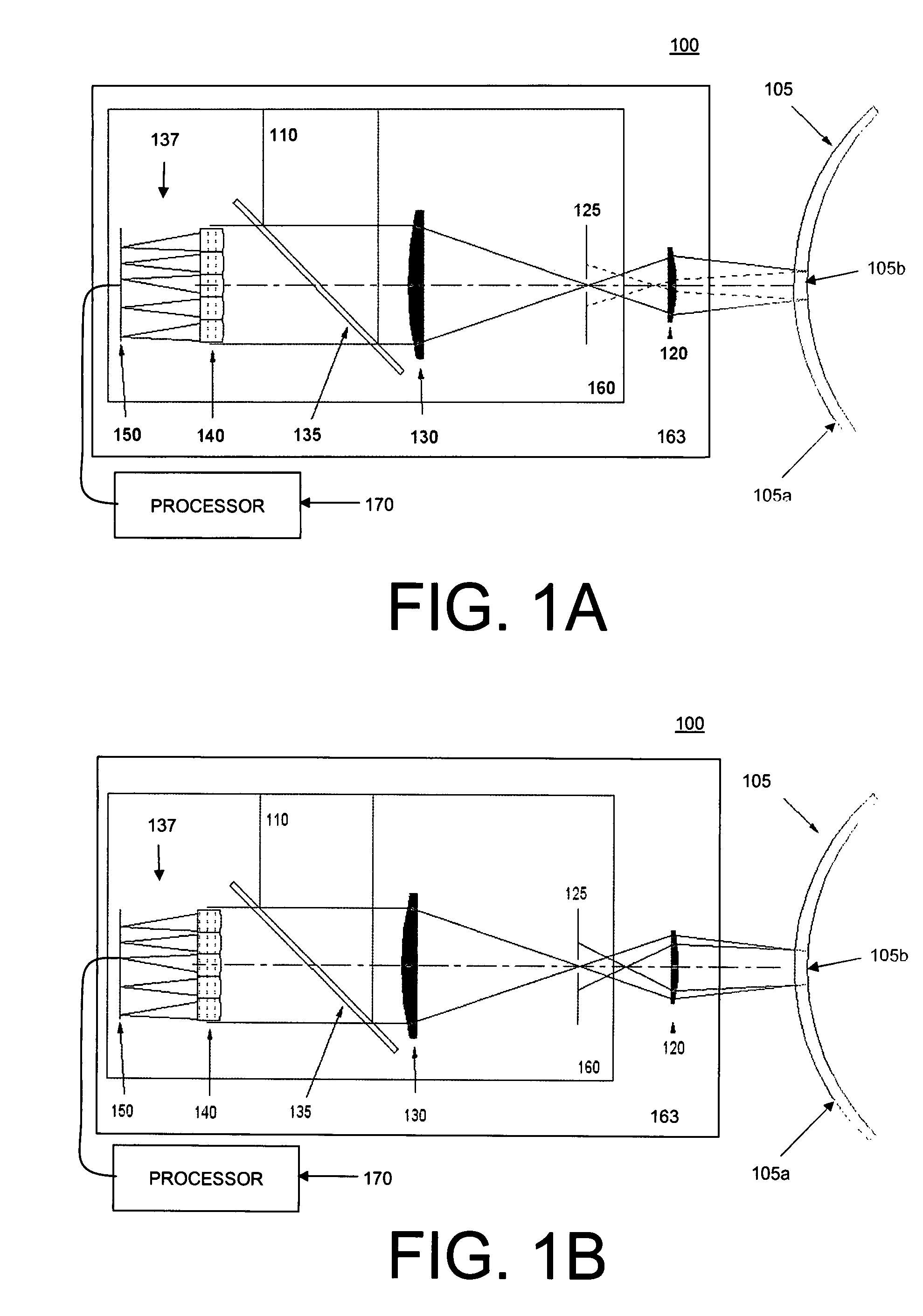
[0030]FIGS. 1A-B functionally illustrate one embodiment of a geometric measurement system 100 for determining at least one geometric characteristic of an object 105, and an associated method of determining at least one geometric characteristic of the object 105, using a wavefront sensor. In particular, the system and method illustrated in ...


PUM


Abstract

A geometric measurement system is adapted to precisely measure one or more surfaces of objects such as corneas, molds, contact lenses in molds, contact lenses, or other objects in a fixture. The geometric measurement system can employ one or more of three possible methods of measurement: Shack-Hartmann wavefront sensing with wavefront stitching; phase diversity sensing; and white light interferometry.

Description

CROSS-REFERENCES TO RELATED APPLICATIONS[0001]This patent application claims the priority benefit under 35 U.S.C. § 119(e) from U.S. provisional patent application 60 / 789,901 filed on 7 Apr. 2006 in the names of Daniel Neal et al., the entirety of which is hereby incorporated herein by reference for all purposes as if fully set forth herein.BACKGROUND AND SUMMARY[0002]1. Field[0003]This invention pertains to the field of measurements, and more particularly, to a geometric measurement system and a method of making geometric measurements of an object using light reflected and / or refracted from one or more surfaces of the object.[0004]2. Description[0005]There are many examples of measurement or metrology systems that are designed to measure or characterize an object's surface. Among these systems are optically-based systems which operate by reflecting or scattering light from the object's surface and then collecting and analyzing the reflected or scattered light. These systems may use...

Claims


Application Information

Patent Timeline
Patent Type & Authority Patents(United States)
IPC IPC(8): G01B11/02
CPCA61B3/1005A61B3/107G01M11/0271G01J9/00G01J9/02G01B11/24
Inventor NEAL, DANIEL R.RAYMOND, THOMAS DANIELPOWERS, WILLIAM SHEA
Owner AMO DEVMENT
Why Eureka
Try Eureka