
Information processing device

a technology of information processing and extension board, which is applied in the direction of coupling device connection, electrical apparatus casing/cabinet/drawer, instruments, etc., can solve the problems of extension board deformation, size of the device, liable to be displaced, etc., to prevent deformation and damage, and prevent displacement and deformation of extension board

Active Publication Date: 2009-09-01
RICOH KK
View PDF9 Cites 1 Cited by
  • Summary
  • Abstract
  • Description
  • Claims
  • Application Information

AI Technical Summary

Benefits of technology

The present invention provides an information processing device that can prevent displacement and deformation of an extension board caused by vibration or shock. This is achieved by providing a supporting member that fixes the extension board and prevents it from falling off or getting bent. The supporting member can be a holding member or an elongated hole and plurality of through-holes. The extension board can be restricted in its arrangement direction by the holding member. The invention prevents damage and deformation of the extension board and ensures reliable support even when it has various shapes.

Problems solved by technology

However, when using this method, the extension board may be deformed by vibration or shock, and is liable to be displaced, and this influences performance of the device.
Especially, when the size of the device and the space occupied by the device is further reduced, the space between constituent components inside the device becomes small, and the extension board may touch components nearby during vibration or shock, and this may deform the extension board.
However, the extension board is not restricted in other directions, and due to this, the extension board may touch components nearby due to vibration or shock.

Method used


Image

  • Information processing device
  • Information processing device
  • Information processing device

Examples


first embodiment

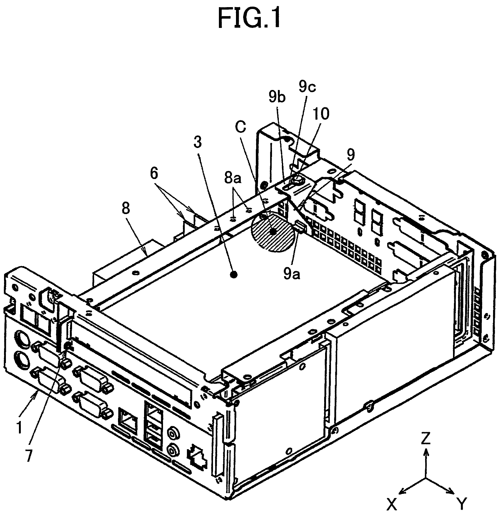
[0038]FIG. 1 is a perspective view of an information processing device according to the present invention.

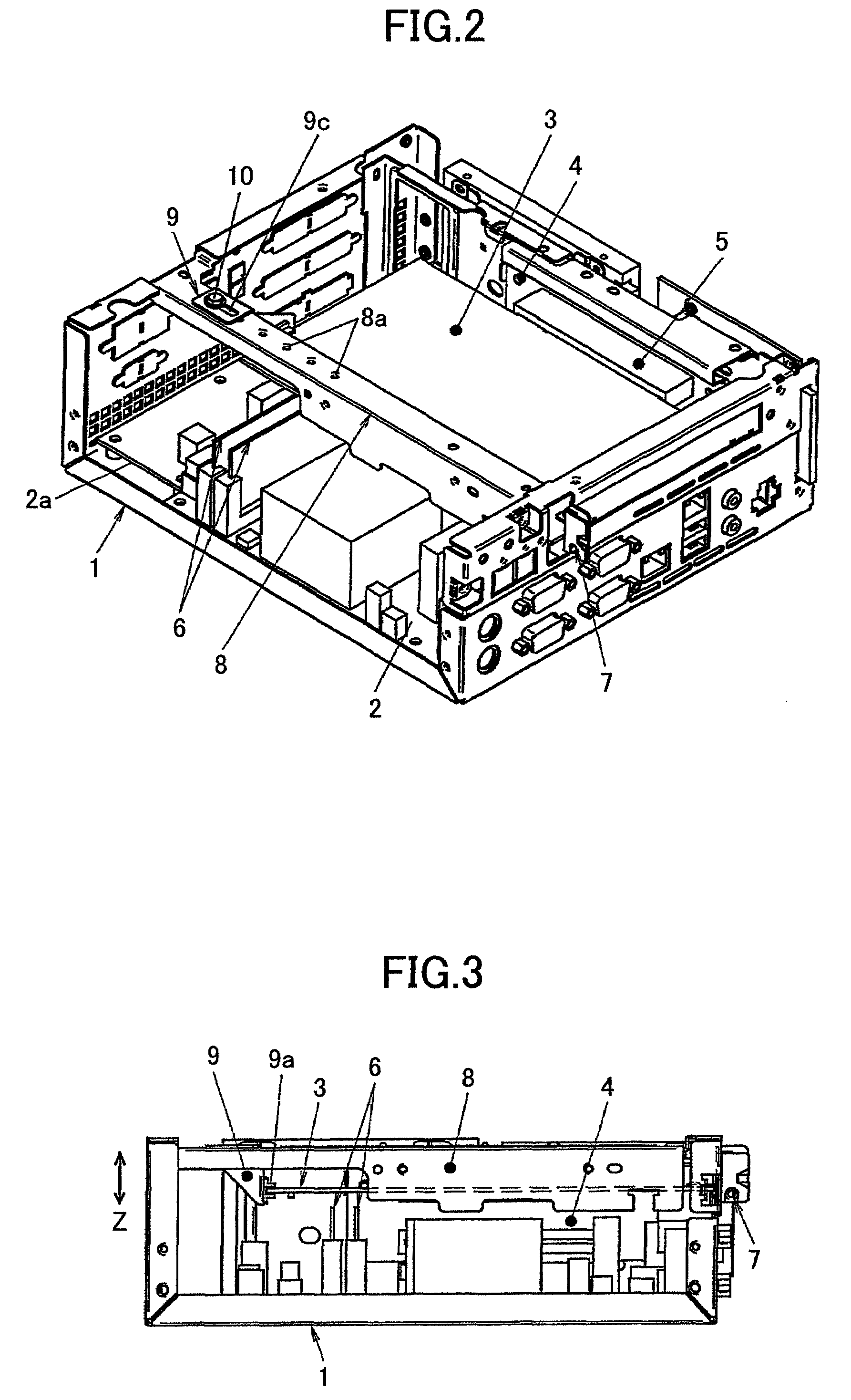
[0039]FIG. 2 is another perspective view of the information processing device according to the present embodiment of the present invention.

[0040]FIG. 3 is a side view of the information processing device according to the present embodiment of the present invention.

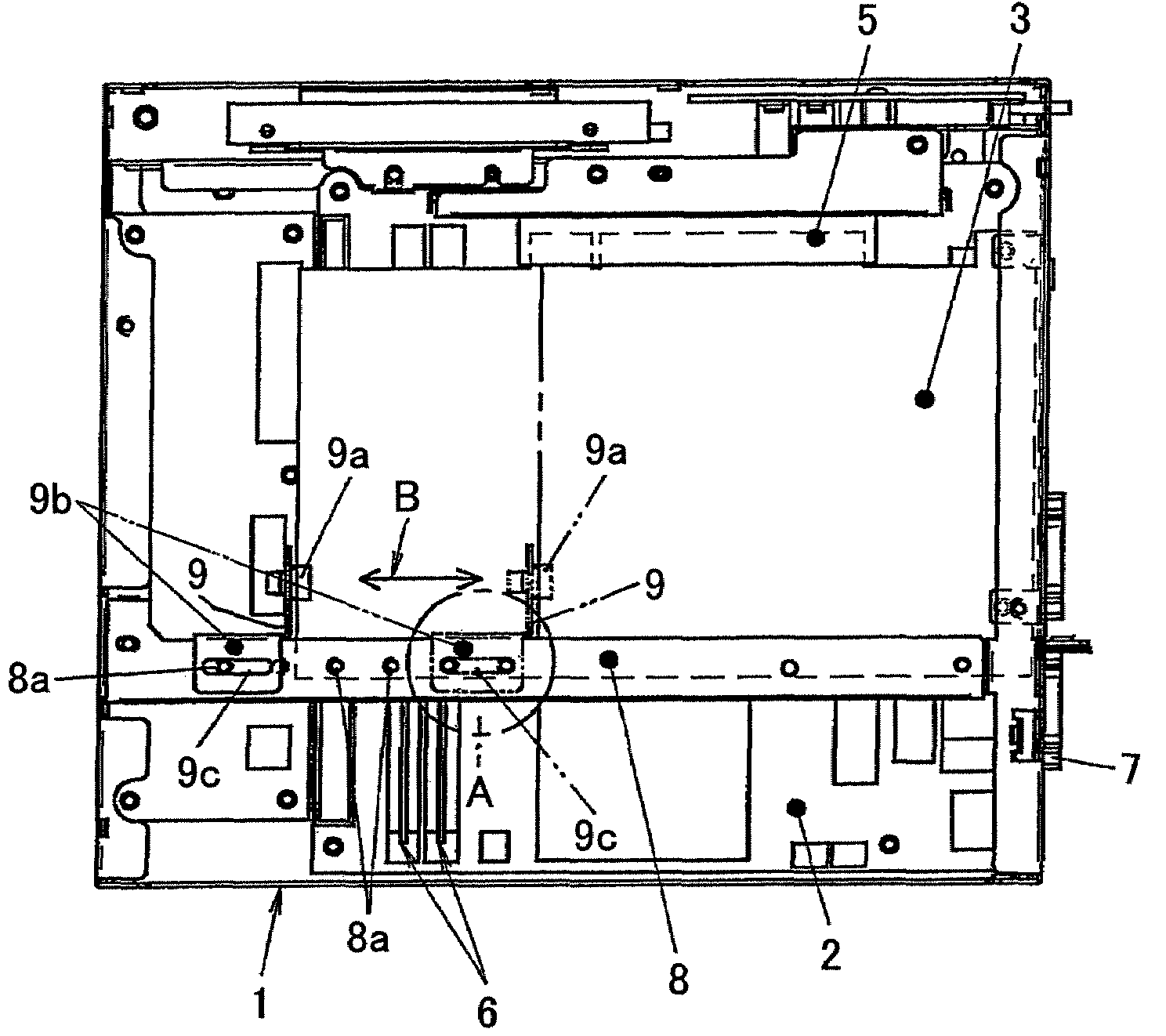
[0041]FIG. 4A is a plan view of the information processing device according to the present embodiment of the present invention.

[0042]FIG. 4B is an enlarged view of a portion A in FIG. 4A.

[0043]As shown in FIG. 1 though FIG. 4B, the information processing device of the present embodiment includes a cover structure 1, serving as a housing, a substrate 2 with a CPU (Central Processing Unit) mounted thereon (hereinafter, the substrate 2 is referred to as a “mother board”), an extension board 3 such as a PCI card, an extension slot changer 4 for changing a direction of mounting the extension board 3 (hereinafter, the extens...

second embodiment

[0051]FIG. 5 is a plan view of an information processing device according to the present invention.

[0052]In FIG. 5, the same reference numbers are assigned to the same elements as illustrated in FIG. 1 through FIG. 4B, and overlapping descriptions are omitted.

[0053]The configuration in FIG. 5 differs from those in FIG. 1 through FIG. 4B in that a holding member 9′ including a holding part 9′a, a supporting portion 9′b, and an elongated hole 9′c is arranged to be parallel to the arrangement direction D of the connector 5 to restrict the side end of the extension board 3 in the arrangement direction D of the connector 5. Therefore, it is possible to present falling-off of the extension board 3 from the connector 5.

[0054]It should be noted that as the structure for holding the extension board 3, the supporting member 8 may be arranged to be perpendicular to parallel to the arrangement direction D of the extension board 3.

[0055]This invention can be applied to a personal computer or an ...


PUM


Abstract

An information processing device is disclosed that is able to prevent displacement of an extension board caused by vibration or shock, and able to prevent deformation of the extension board and members nearby. The information processing device includes a substrate with a CPU (Central Processing Unit) mounted thereon, a housing that accommodates the substrate, an extension board arranged to be parallel to the substrate, and a supporting member that is fixed on the housing and is arranged to be parallel to at least one end surface of the substrate so that the supporting member supports the extension board.

Description

BACKGROUND OF THE INVENTION[0001]1. Field of the Invention[0002]The present invention relates to an information processing device including a substrate with a CPU (Central Processing Unit) attached thereto and an extension board.[0003]2. Description of the Related Art[0004]It is required that a personal computer or an embedded controller be compact and occupy a small space, even when they are desktop devices. In the desktop devices, usually, a PCI (Peripheral Component Interconnect) card, which is an extension board, is embedded in order to extend functions not normally provided by the devices.[0005]Usually, the extension board is fixed by screwing at one position of a non-engagement portion of a connector. However, when using this method, the extension board may be deformed by vibration or shock, and is liable to be displaced, and this influences performance of the device.[0006]Especially, when the size of the device and the space occupied by the device is further reduced, the spac...

Claims


Application Information

Patent Timeline
Patent Type & Authority Patents(United States)
IPC IPC(8): H05K7/02H05K7/04
CPCG06F1/184H01R13/73G06F1/186G06F1/185
Inventor WATANABE, HAYATO
Owner RICOH KK
Learn More