AI technical title is built by Patsnap AI team. It summarizes the technical point description of the patent document.
a technology of environmental monitoring and laser, which is applied in the field of monitoring systems, can solve the problems of unrealistically high electrical energy consumption, commercial impracticality, and inability to commercially practical femtosecond lasers until recently, and achieves the effects of minimizing the spread of the agent, fast and real-time analysis and feedback, and cost-effectiveness
Active Publication Date: 2009-09-01
BOARD OF TRUSTEES OPERATING MICHIGAN STATE UNIV
View PDF111 Cites 37 Cited by
Summary
Abstract
Description
Claims
Application Information
AI Technical Summary
This helps you quickly interpret patents by identifying the three key elements:
Problems solved by technology
Method used
Benefits of technology
Problems solved by technology
Commercially practical femtosecond lasers have been unavailable until recently.
For example, lasers which can generate 10 femtosecond or less laser pulse durations have traditionally been extremely expensive, required unrealistically high electrical energy consumption (for extensive cooling, by way of example) and depended on laser dyes that had to be replenished every month thereby leading to commercial impracticality.
Ultrashort pulses are prone to suffer phase distortions as they propagate through or reflect from optics because of their broad bandwidth.
These shaped pulses require a very large data set and in many cases, complex learning calculations for determining the pulse shaping characteristics for a particular application.
Since the variation shape of the possible pulse shapes is huge, scanning the entire parameter space is impossible and as such the optimized pulse shape could not have been predicted by theory.
This dataset is extremely large, therefore, while in principle, the field exists to achieve the desired photonic transformation or excitation, finding it is a great challenge.
Conventional devices are only designed for use to detect a single known agent or are inaccurate.
Method used
Image
Click on the blue label to locate the original text in one second.
Reading with bidirectional positioning of images and text.
Examples
Embodiment Construction
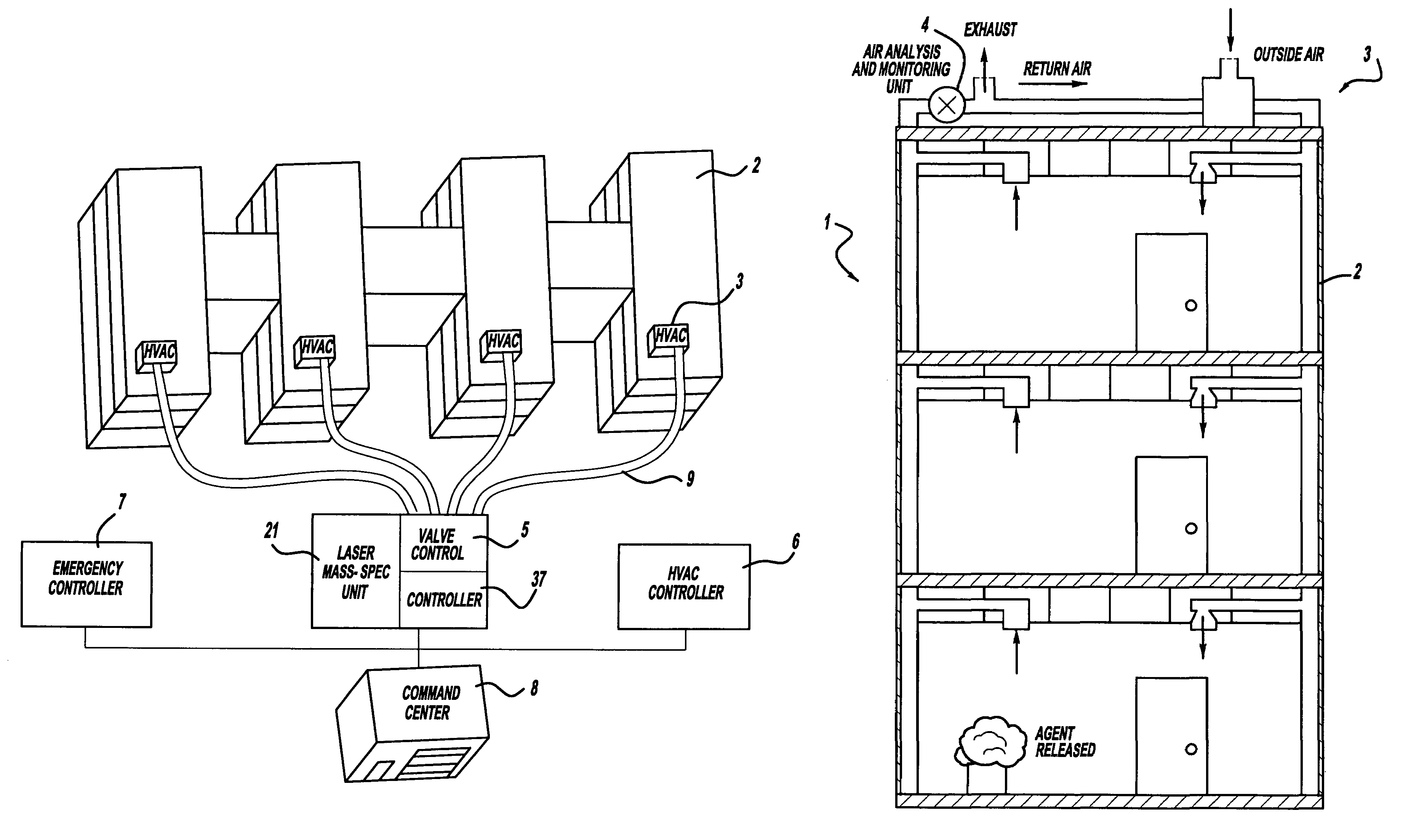
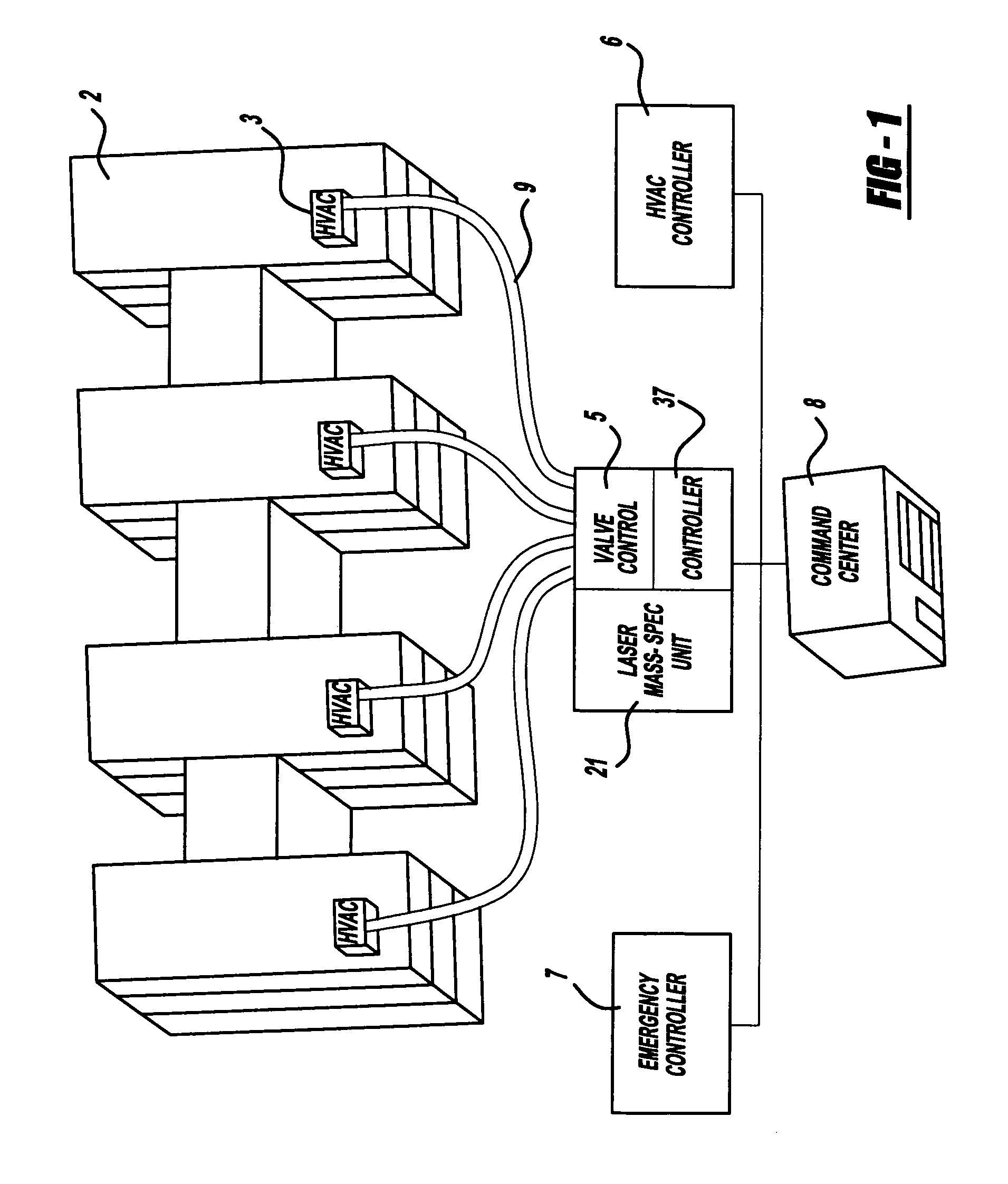
[0023]A laser and environmental monitoring system 1 is provided to monitor airborne chemical and biological agents in the desired environmental specimen or target area. This unit, because of its sensitivity, can be used to sense smoke from a fire. Referring to FIG. 1, a first preferred embodiment system 1 of the present invention includes a multi-story building 2, having a plurality of wings with interconnecting hallways, with each wing having separate ventilating systems, such as heating / ventilating / air conditioning climate control units (hereinafter “HVAC” units) 3. A laser and detection apparatus 21 is housed in a self-contained unit 4 with inlet valve controls 5. Furthermore, an HVAC control unit 6, a fire door / alarm / sprinkler emergency control unit 7 and a remote command center 8, such as a public safety or fire department 8, are also provided. Laser and detection apparatus 21 includes a femtosecond laser, pulse shaping optics, a mass spectrometer and a computer controller 37 a...
PUM
Property
Measurement
Unit
energy
aaaaa
aaaaa
central wavelength
aaaaa
aaaaa
acoustic velocity
aaaaa
aaaaa
Abstract
A laser and monitoring system is provided. In another aspect of the present invention, the system includes a laser, pulse shaper and detection device. A further aspect of the present invention employs a femtosecond laser and binary pulse shaping (BPS). Still another aspect of the present invention uses a laser beam pulse, a pulse shaper and a SHG crystal. In yet another aspect of the present invention, a multiphoton intrapulse interference phase scan (hereinafter “MIIPS”) method is used to characterize the spectral phase of femtosecond laser pulses and to correct them. A further aspect of the system of the present invention is employed to monitor environmental chemicals and biological agents, including toxins, explosives, and diseases.
Description
CROSS REFERENCE TO RELATED APPLICATIONS[0001]This is a continuation-in-part of Ser. No. 10 / 791,377, filed Mar. 2, 2004, which is a continuation-in-part of Ser. No. 10 / 265,211, filed Oct. 4, 2002, which is a continuation-in-part of PCT / US02 / 02548, filed Jan. 28, 2002, which claims priority to provisional application 60 / 265,133, filed Jan. 30, 2001. Furthermore, this is continuation-in-part of Ser. No. 10 / 265,211, filed Oct. 4, 2002, which is a continuation-in-part of PCT / US02 / 02548, filed Jan. 28, 2002, which claims priority to provisional application 60 / 265,133, filed Jan. 30, 2001. This is also a continuation-in-part of Ser. No. 10 / 628,874, filed Jul. 28, 2003, which is a continuation of PCT / US02 / 02548, filed Jan. 28, 2002, which claims priority to provisional application 60 / 265,133, filed Jan. 30, 2001. All of these applications are incorporated by reference herein.BACKGROUND[0002]The present invention generally relates to a monitoring system and more particularly to a laser and e...
Claims
Application Information
Patent Timeline
Application Date:The date an application was filed.
Publication Date:The date a patent or application was officially published.
First Publication Date:The earliest publication date of a patent with the same application number.
Issue Date:Publication date of the patent grant document.
PCT Entry Date:The Entry date of PCT National Phase.
Estimated Expiry Date:The statutory expiry date of a patent right according to the Patent Law, and it is the longest term of protection that the patent right can achieve without the termination of the patent right due to other reasons(Term extension factor has been taken into account ).
Invalid Date:Actual expiry date is based on effective date or publication date of legal transaction data of invalid patent.

