
Method and apparatus for embolism analysis

a technology of embolism and analysis method, applied in image analysis, image enhancement, instruments, etc., can solve the problems of blood clots, treatment also carrying risks, and assessment may not be automated,

Inactive Publication Date: 2009-09-01
SIEMENS MEDICAL SOLUTIONS USA INC +1
View PDF13 Cites 18 Cited by
  • Summary
  • Abstract
  • Description
  • Claims
  • Application Information

AI Technical Summary

Benefits of technology

The present invention provides an automated technique for analyzing the affected region due to an embolism in an organ. This involves generating a segmented image of the organ vasculature and identifying the embolus within the image. The volume of the organ affected by the embolism is then determined by computing a sub-tree within the segmented image and removing unwanted overlapping trees. The process may be iterated by identifying additional emboli and calculating the percentage of the organ perfused by each embolus. This technique allows for more accurate and efficient analysis of embolism in organs.

Problems solved by technology

Blood clots are the most common cause of embolism.
However, treatments also carry risks, so correct diagnosis is critical.
This high resolution three dimensional data offers the potential for precise analysis of the effects of PEs on the lungs, but such assessments may be infeasible without automation.
However a disadvantage is that in order to properly measure perfusion, two scans are required, before and after contrast, requiring a complicated acquisition and twice as much radiation.
In addition, non-rigid registration is required to align the two scans, which is difficult and time-consuming.

Method used


Image

  • Method and apparatus for embolism analysis
  • Method and apparatus for embolism analysis
  • Method and apparatus for embolism analysis

Examples


Embodiment Construction

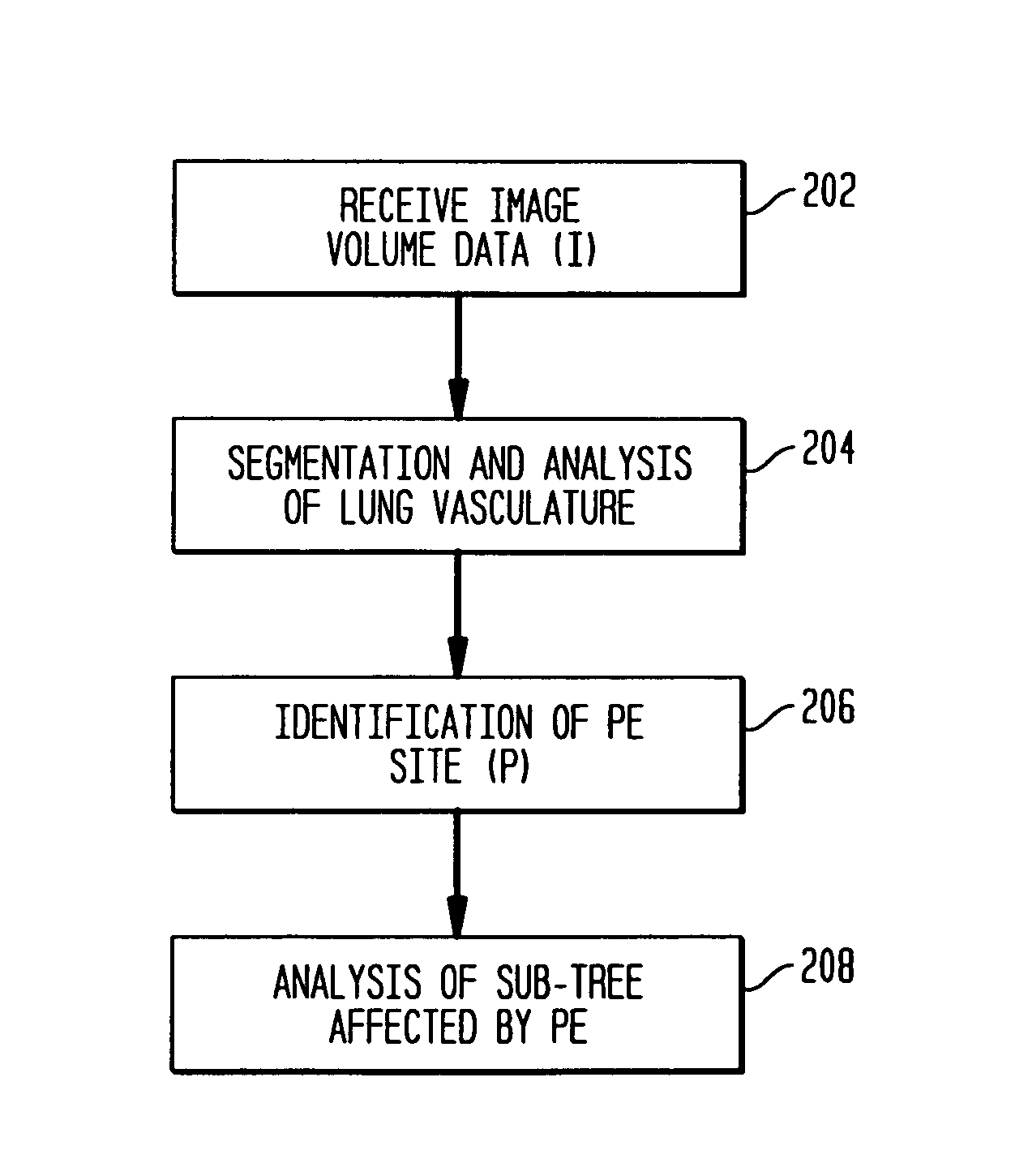
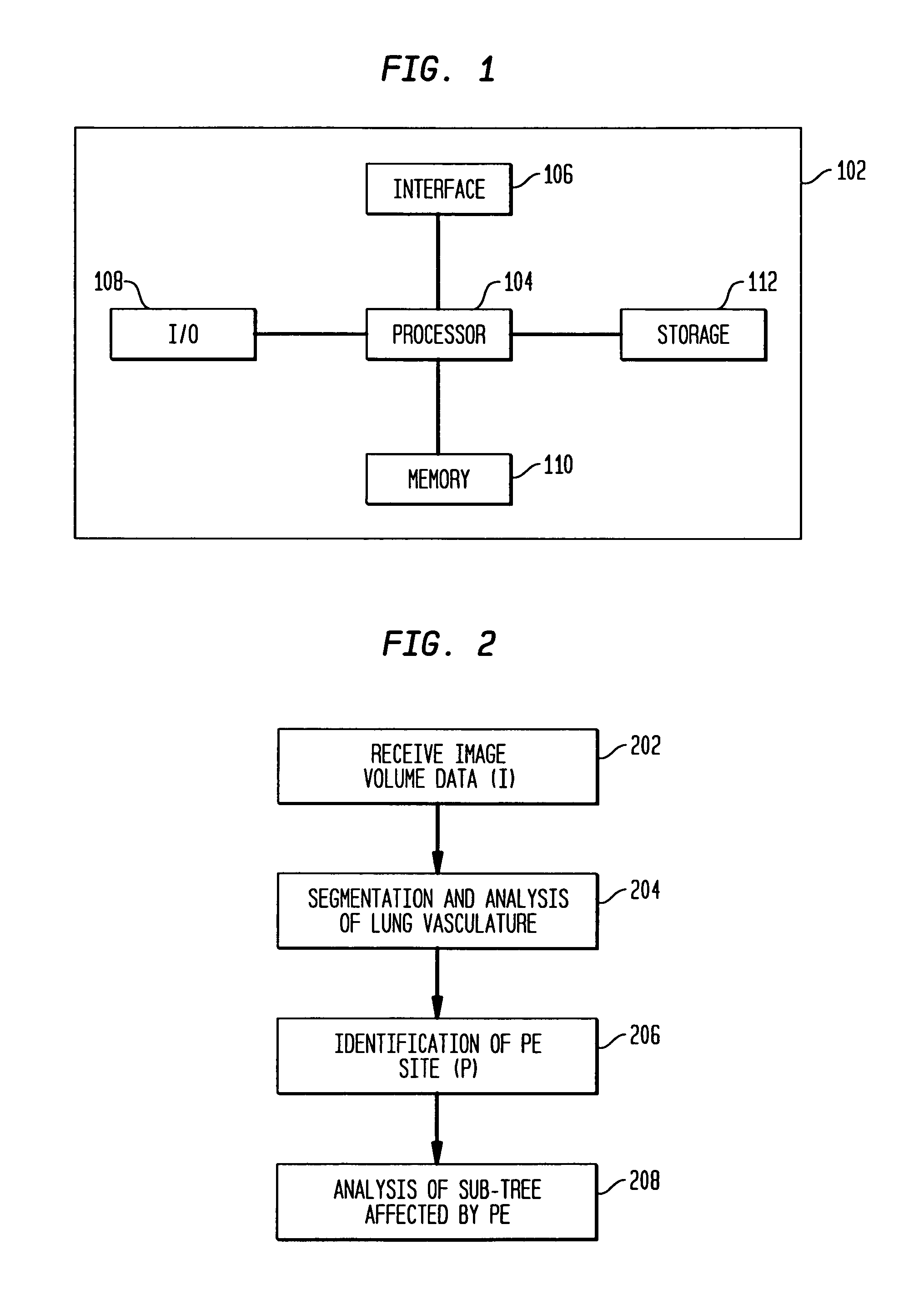
[0024]The following description describes the present invention in terms of the processing steps required to implement an embodiment of the invention. These steps may be performed by an appropriately programmed computer, the configuration of which is well known in the art. An appropriate computer may be implemented, for example, using a well known computer processors, memory units, storage devices, computer software, and other components. A high level block diagram of such a computer is shown in FIG. 1. Computer 102 contains a processor 104 which controls the overall operation of computer 102 by executing computer program instructions which define such operation. The computer program instructions may be stored in a storage device 112 (e.g., magnetic disk) and loaded into memory 110 when execution of the computer program instructions is desired. Computer 102 also includes one or more interfaces 106 for communicating with other devices (e.g., locally or via a network). Computer 102 al...


PUM


Abstract

Disclosed is an automated technique for analyzing the affected region due to an embolism in an organ. A segmented image of the organ vasculature is generated using image volume data received, for example, from a Computed Tomography (CT) machine. An embolus is then identified (either manually or automatically) within the segmented image, and the volume of the organ affected by the embolism is automatically determined. The volume of the organ affected by the embolism may be determined by computing a sub-tree within the segmented image, where the sub-tree comprises vessels that are distal to the identified embolus point. In one embodiment, the sub-tree is generated by determining a plane perpendicular to a vessel at the embolus point such that the sub-tree comprises a distal portion of the vasculature with respect to the plane. Unwanted overlapping trees are identified (e.g., by analyzing branch angles) and removed from the sub-tree. The volume of the organ affected by the embolism is determined by calculating a volume of the organ that is perfused by the sub-tree. The affected volume may be adjusted by scaling the volume based on the percentage occlusion of the partial embolus.

Description

[0001]This application claims the benefit of U.S. Provisional Application No. 60 / 609,521 filed Sep. 13, 2004, which is incorporated herein by reference.BACKGROUND OF THE INVENTION[0002]The present invention relates generally to analysis of emboli, and more particularly to automatically analyzing the affected region due to an embolism in an organ.[0003]Embolism is the obstruction of a blood vessel by a foreign substance. Blood clots are the most common cause of embolism. A pulmonary embolus is a blood clot that has been carried through the blood stream into a pulmonary artery (blood vessels proceeding from the heart into the lungs) partially or fully blocking that vessel. The term “embolus” refers to the plug obstructing the blood vessel while embolism refers to the process by which this happens.[0004]Although Pulmonary Embolism (PE) is a common causes of unexpected death, it may often be preventable. Prompt treatment with anti-coagulants is essential to prevent loss of life. However...

Claims


Application Information

Patent Timeline
Patent Type & Authority Patents(United States)
IPC IPC(8): G06K9/00
CPCG06T7/0012G06T7/0081G06T7/602A61B6/507G06T2207/20101G06T2207/20141G06T2207/30101G06T2207/10081G06T7/11G06T7/62G06T7/187
Inventor KIRALY, ATILLA PETERNOVAK, CAROL L.GUNDEL, LUTZ
Owner SIEMENS MEDICAL SOLUTIONS USA INC
Learn More