Universal remote terminal unit and method for tracking the position of self-propelled irrigation systems

a technology of self-propelled irrigation and remote terminal, which is applied in the direction of liquid transfer devices, instruments, navigation instruments, etc., can solve the problems of common unplanned stoppages, irrigation systems to stop, and substantial crop loss, so as to improve reliability, simple electric current sensor, and low cost

Active Publication Date: 2009-09-01
HAALAND KARLYLE
View PDF10 Cites 44 Cited by
  • Summary
  • Abstract
  • Description
  • Claims
  • Application Information

AI Technical Summary

Benefits of technology

[0015]A simple “current sensor” is used by the present invention to detect movement of an outer drive tower and thereby pivot running status (on or off). The current sensor device is standard and readily available. The current sensor need only be positioned around a single, insulated conductor of an electrical circuit that is continuously or intermittently conducting AC current (i.e., cycling on and off over several minutes of time) whenever the pivot is moving. The present invention completely eliminates the need for any hard-wire connections between the circuitry of a remote terminal unit (RTU) and the AC control or power circuits of the center pivot irrigation system in order to establish pivot on / off status. Use of a current sensor and specific microprocessor logic enables the universal RTU of the present invention to determine if a center pivot sprinkler is running (moving) or is stopped. The use of a current sensor by the system and method of the present invention along with a stand alone GPS receiver eliminates a hard-wired interface with the existing control or power circuits—i.e., the present invention comprises a truly “wireless” interface remote monitoring system. The current sensor device need only be positioned around a conducting wire (e.g., over the plastic insulation of the wire).
[0039]It is a further object of the present invention to provide a universal, self-contained, wireless interface remote monitoring system that is economical to manufacture; simple to install and relocate; efficient in use; capable of being retrofit to any of a number of different center pivot irrigation systems without modification; reliable; and well suited to operate on both center pivots and linear move systems in all environments, anywhere in the world.

Problems solved by technology

Factors such as soil type, soil water intake rate, slope, water availability, energy costs, flotation for wheels and land obstacles affect the use of such systems.
An unnoticed shutdown may result in substantial loss of the crop.
Such applications typically take three to four days to complete and longer for larger fields.
Unplanned stoppages are common due to field conditions (stuck wheels) and mechanical and electrical malfunction (broken drive lines, failed electro-mechanical devices, etc.).
Water delivery systems also breakdown and cause irrigation systems to stop.
Electrical power outages and deliberate load shed schemes by power providers can cause hundreds of irrigation systems to shutdown at any hour of the day.
Water delivery systems powered by natural gas engines are subject to gas line pressure fluctuations that can cause internal combustion engines to shutdown, resulting in loss of water delivery and a center pivot shutdown.
Furthermore, the sensitive electronics and radios needed to remotely monitor pivot status by this hard-wired method are easily interfered with and can be damaged from improper installation, electrical power surges and lightning events.
As a result, the systems tend to be costly to manufacturer, install and maintain.
These types of remote monitoring and control systems are expensive and are often impractical on older pivots without extensive upgrades to the pivot point and the pivot controls.
Many lack proper documentation to facilitate the proper interface of circuitry wires required with traditional remote monitoring devices.

Method used


Image

  • Universal remote terminal unit and method for tracking the position of self-propelled irrigation systems
  • Universal remote terminal unit and method for tracking the position of self-propelled irrigation systems
  • Universal remote terminal unit and method for tracking the position of self-propelled irrigation systems

Examples


Embodiment Construction

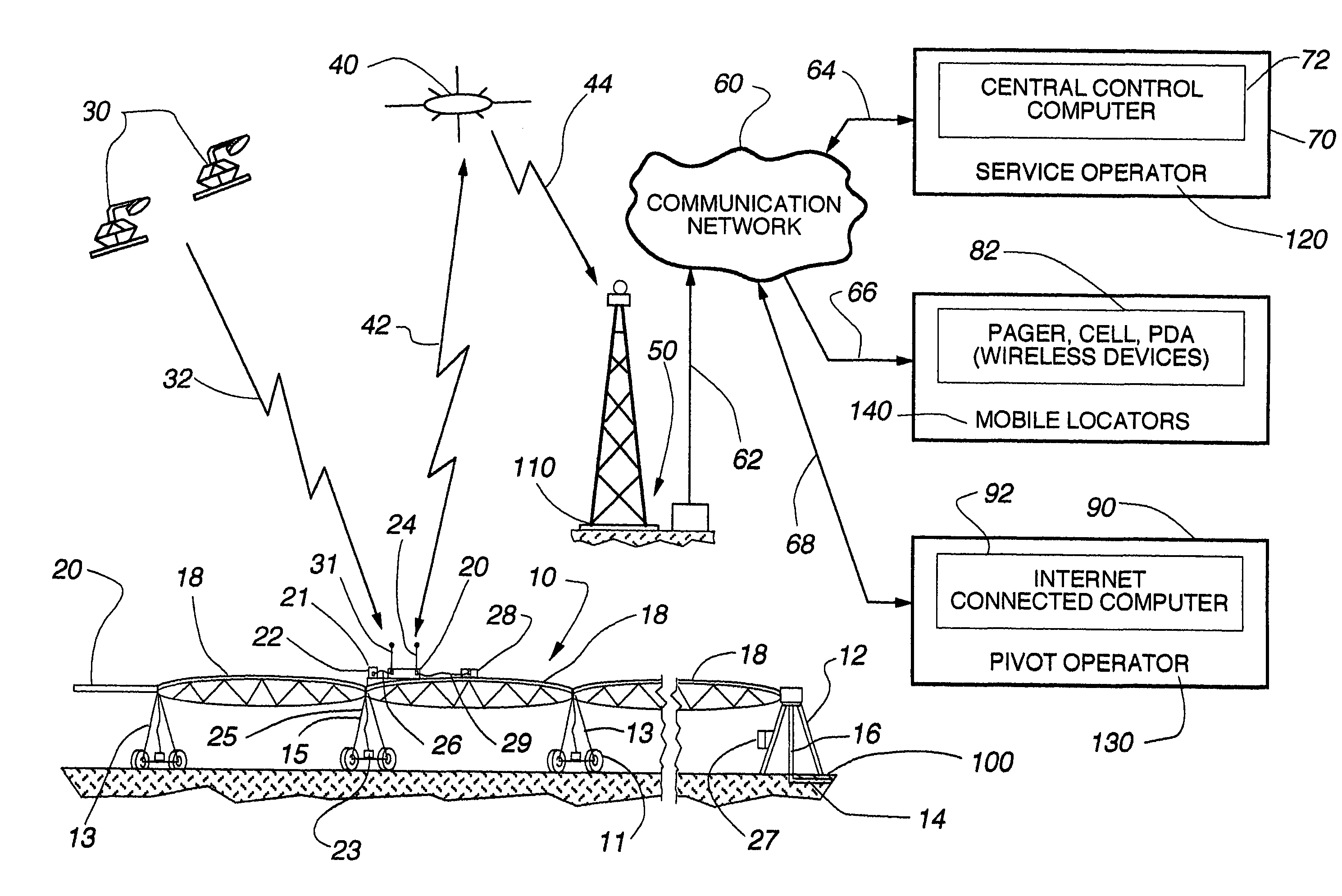
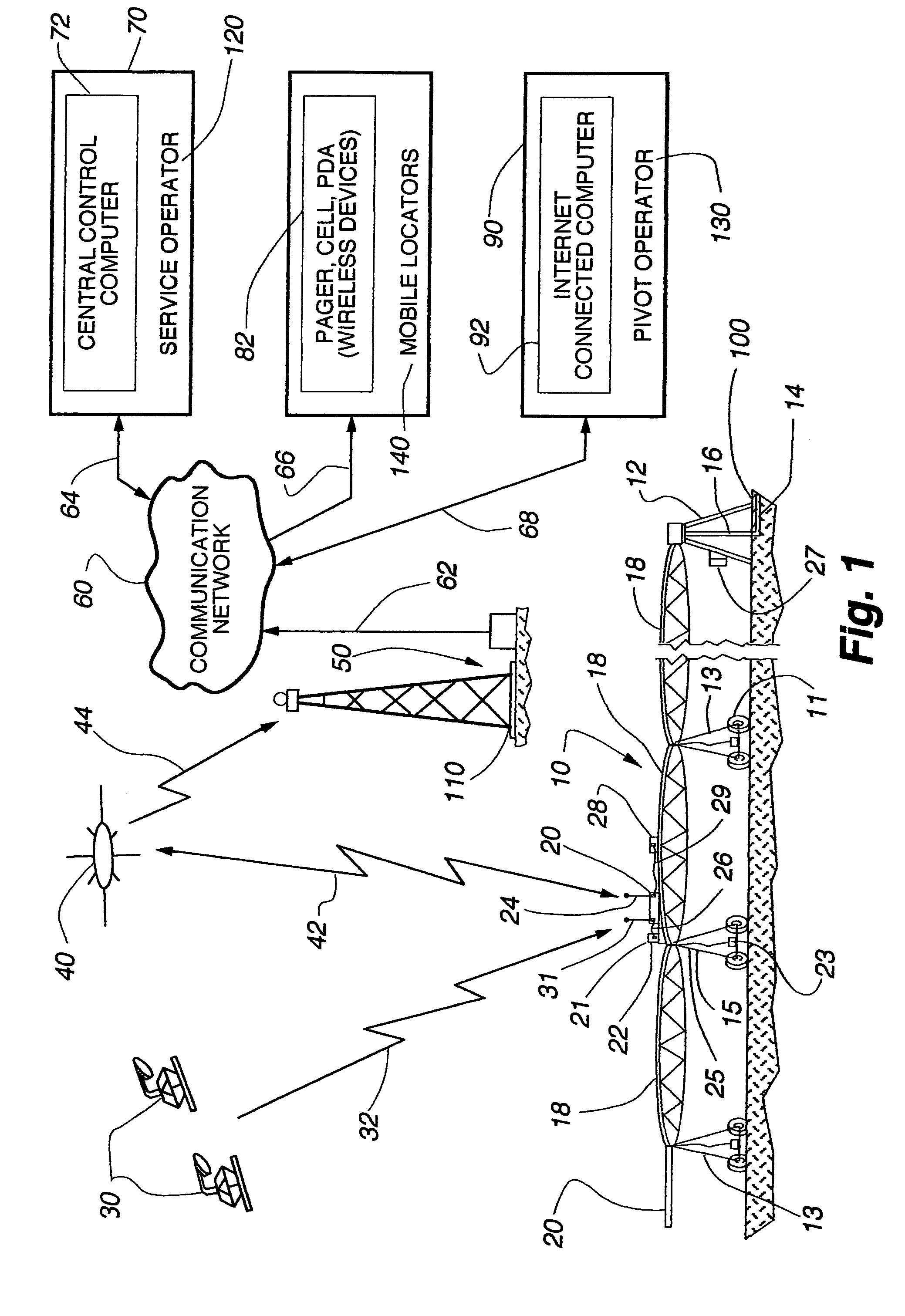
[0056]The system of the present invention is illustrated in FIG. 1 as being connected to a center pivot or lateral mechanized irrigation system 10 (herein sometimes simply referred to as “pivot” or “center pivot”). The invention includes a universal, self-contained remote terminal unit (RTU) with global position satellite (GPS) receiver 20 which receives signals 32 from GPS positioning satellites 30. The remote terminal unit is further connected 42 to a low orbit data communication satellite 40, a ground station 50, a communication network 60, a service operator location 120, multiple mobile locations 140, and a remote pivot operator monitoring location 130.

[0057]Mechanized irrigation systems 10 are conventional and commercially available from a number of different manufacturers. Mechanized irrigation systems 10 are commonly used in a center pivot configuration such as shown in FIG. 1 wherein the center pivot point 12 extracts pressurized water 14 for delivery through a fluid delive...


PUM


Abstract

A universal remote monitoring system and method for irrigation systems having a self-contained remote terminal unit mounted at an outer portion of the irrigation system which is independent of the irrigation system control. The unit includes a global positioning system for producing coordinate data, a computer for processing the coordinate data into operational data, and a transmitter for delivering the operational data to a communications satellite. The satellite relays the operational data through a communications network into a remote service computer which generates information messages to mobile operator devices informing the operator of movement status and other operational information.

Description

RELATED APPLICATIONS[0001]This application claims the benefit of U.S. Provisional Patent Application Ser. No. 60 / 598,950 filed Aug. 5, 2004; U.S. Provisional Patent Application Ser. No. 60 / 613,773 filed Sep. 28, 2004 and U.S. Provisional Patent Application Ser. No. 60 / 695,076 filed Jun. 29, 2005.BACKGROUND OF THE INVENTION[0002]1. Field of the Invention[0003]The present invention relates generally to center pivot and lateral move irrigation systems. More specifically, the present invention relates to a remote monitoring unit which senses movement or non-movement of the irrigation system over a span of time to determine operating status (running or stopped), to determine pivot arm position (e.g., location of last wheel set) and to remotely sense water delivery through the span pipes to determine wet / dry status. The remote monitoring unit is self-contained without having to hard-wire directly to any existing control or other electrical circuits of the irrigation system.[0004]2. Discus...

Claims


Application Information

Patent Timeline
Patent Type & Authority Patents(United States)
IPC IPC(8): B05B12/00
CPCA01G25/16A01G25/092
Inventor ABTS, GERALD L.
Owner HAALAND KARLYLE
Why Eureka
Try Eureka