Vertical cyclonic vacuum assembly

a vacuum assembly and cyclonic technology, applied in the direction of carpet cleaners, cleaning filter means, separation processes, etc., can solve the problems of less efficiency of vacuum, the attachment of the handle portion to the cyclonic portion, etc., and achieve the effect of convenient cleaning or disposal, simple and efficient, and easy to pull out and empty

Inactive Publication Date: 2009-09-08
F V S
View PDF14 Cites 70 Cited by
  • Summary
  • Abstract
  • Description
  • Claims
  • Application Information

AI Technical Summary

Benefits of technology

[0020]It is envisioned that the preferred embodiment will comprise an additional filter assembly having a plurality of filters placed in the vacuum to further ensure a greater entrapment of particles. It is a further object of the present invention to provide a simple and an efficient means to clean the dirt assembly and empty the particles contained within it. This is accomplished through dirt collection assembly portion that opens by means of a handle wherein the container held within can be easily pulled out and emptied. The dirt collection assembly forms a receptacle that cannot be removed unless a lock placed above it is flipped to disengage the container sealed in a secure position within the cyclonic portion.
[0021]It is an advantage to the present invention to comprise the vacuum with a moving bumper that opens a slot to collect dust at the base boards or the edges of the furniture that are typically difficult to reach. It is envisioned that the moving bumper is a nylon or a nylon overmolded with a rubber surface. The bumper will not scratch or dent the woods or the furniture it bumps.
[0022]It is another advantage to the present invention that the brushroll sleeves can be easily pulled out for cleaning or disposal. It is envisioned that either reusable or durable, inexpensive, disposable sleeves can be utilized.
[0023]It is another advantage to the present invention to design a handle that folds downwards when the vacuum is not utilized so that it will not occupy the entire storage space, but rather, it will only occupy the lower space of a closet.
[0024]A final advantage to the present invention is its light weight construction and design.
[0025]In an alternate embodiment to the present invention, it is envisioned that a user can lock the dirt assembly portion to the handle portion so that the dirt assembly will fall to a horizontal position when the user wants the vacuum to reach deep spaces, i.e. those spaces under furniture.

Problems solved by technology

These and many other vacuum cleaners comprise stand-up cyclonic dirt assembly portions; however, a disadvantage to all of their designs is that the handle portion is attached to these cyclonic portions.
The vacuum becomes less efficient as it is pushed into the horizontal position.

Method used


Image

  • Vertical cyclonic vacuum assembly
  • Vertical cyclonic vacuum assembly
  • Vertical cyclonic vacuum assembly

Examples


Embodiment Construction

[0039]The best mode for carrying out the invention is presented in terms of its preferred embodiment, herein depicted within the Figures.

DETAILED DESCRIPTION OF THE FIGURES

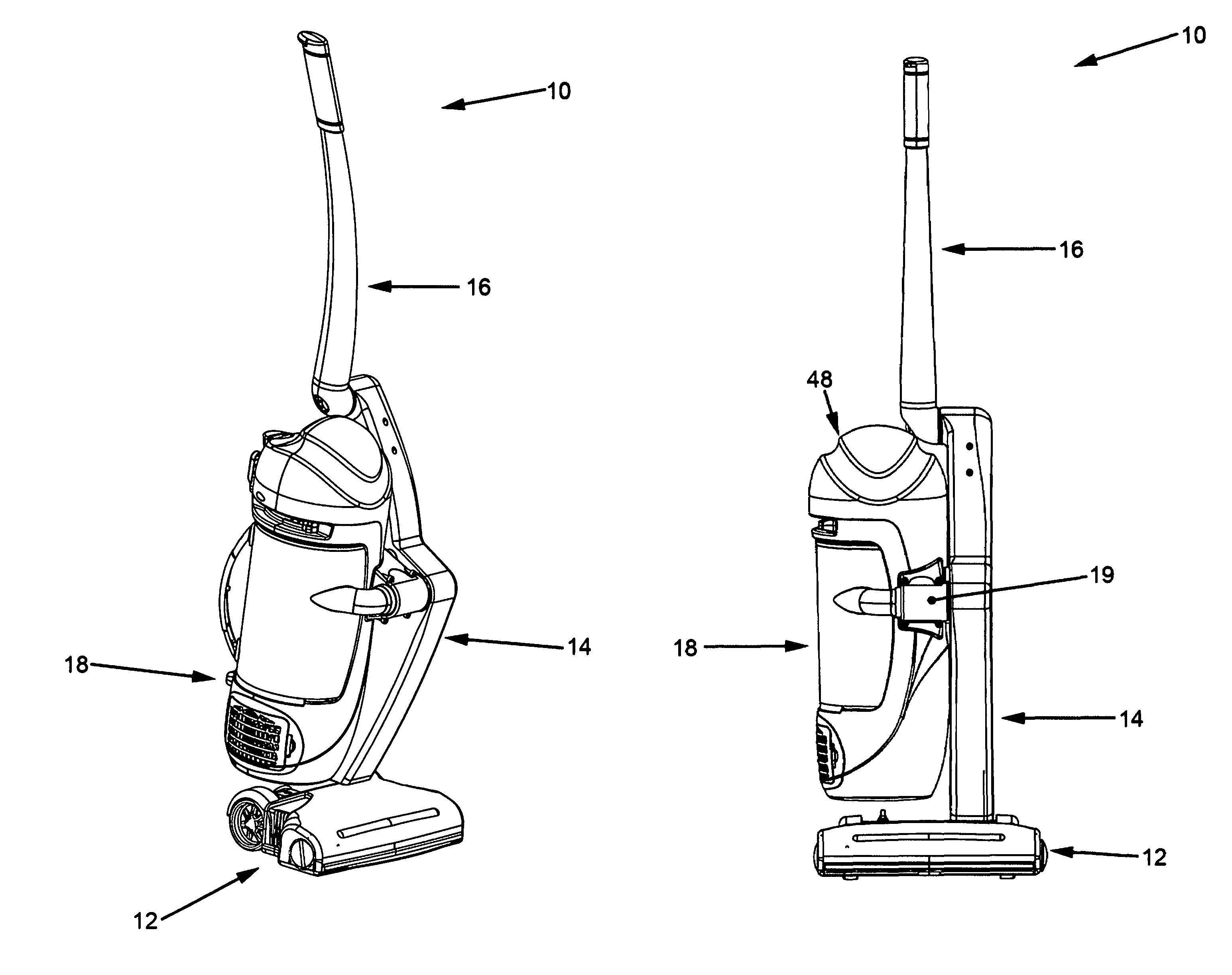
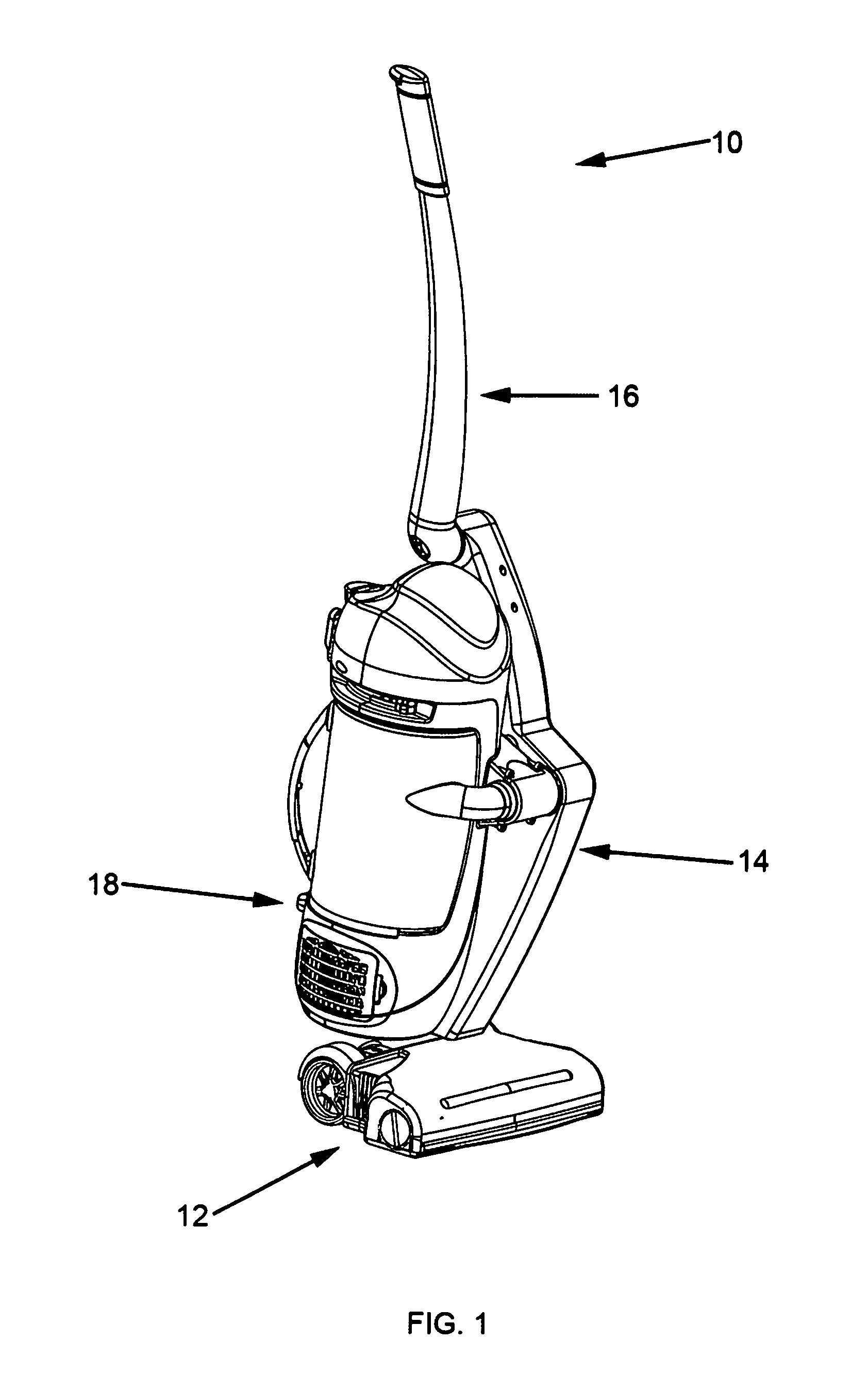
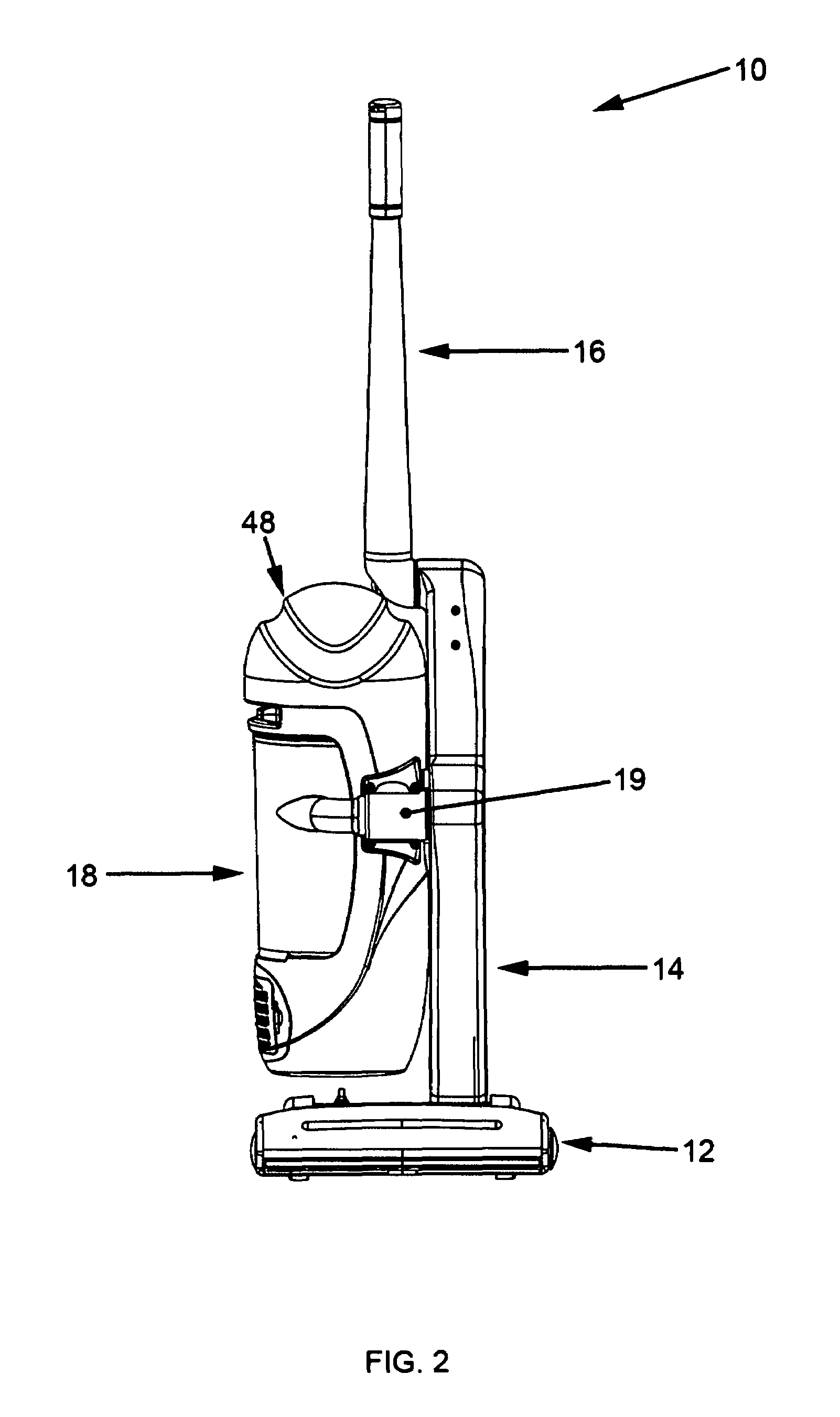
[0040]Referring now to FIG. 1, a vertical cyclonic vacuum assembly, generally noted as 10, is shown according to the preferred embodiment of the present invention. The vacuum assembly 10 comprises a power brush (herein synonymously referred to as a power foot) 12 at a lower end and opposite a handle 16 at an upper end. Both the power foot 12 and the handle 16 are attached to a frame 14. A cyclonic assembly 18 is pivotally attached to the frame 14 such as to maintain a vertical configuration at the handle 16 is articulated upward or downward in a manner described in greater detail below. As shown in conjunction with FIG. 2, the front of the vacuum 10 shown wherein the cyclonic assembly 18 is pivotally attached to the frame 14 at their approximate center body portions about an axis 19. As can be better seen in conju...


PUM

PropertyMeasurementUnit
weightaaaaaaaaaa
lengthaaaaaaaaaa
anglesaaaaaaaaaa

Abstract

The present invention relates to a cyclonic vacuum cleaner and, more specifically, to a cyclonic vacuum cleaner having a cyclonic station that maintains a vertical position when the vacuum is maneuvered across a floor space. The instant abstract is neither intended to define the invention disclosed in this specification nor intended to limit the scope of the invention in any way.

Description

RELATED APPLICATIONS[0001]Not Applicable.BACKGROUND OF THE INVENTION[0002]1. Field of the Invention[0003]The present invention relates to a cyclonic vacuum cleaner and, more specifically, to a cyclonic vacuum cleaner having a cyclonic station that maintains a vertical position when the vacuum is maneuvered across a floor space.[0004]2. Description of the Related Art[0005]In the last decade, the convenience of bagless dust collection and emptying has made cyclonic vacuum cleaners the most successful ones marketed because they don't require consumers to purchase replacement bags. The method of removing particles from the air by means of cyclonic separation is well known in the art and, furthermore, its known uses, in combination with filters, have improved the design, the quality and the efficiency of vacuum cleaners. The present invention improves on the cyclonic design by constructing a cyclonic station that always maintains a complete, vertical position when the vacuum is pushed an...

Claims


Application Information

Patent Timeline
Patent Type & Authority Patents(United States)
IPC IPC(8): A47L9/10A47L9/16A47L9/32
CPCA47L5/30A47L9/325A47L9/02A47L9/009Y10S55/03
Inventor WEETER, DARRELLSCHROEDER, WESLEYSCHOLLES, BENJAMIN
Owner F V S
Why Eureka
Try Eureka