Container for disk drives

a technology for containers and drives, applied in the field of containers or packages, can solve the problems of increasing motor noise, bearing/race damage, and disks to partially rotate in repetitive back and forth motions, and achieve the effect of reducing the overall height of the insert, increasing the effective height of each cushioning rib, and reducing the overall size of the container

Inactive Publication Date: 2009-09-08
SEAGATE TECH LLC
View PDF35 Cites 68 Cited by
  • Summary
  • Abstract
  • Description
  • Claims
  • Application Information

AI Technical Summary

Benefits of technology

[0010]In accordance with the present invention, a container or package for multi-disk drive shipping is provided that adequately protects the disk drives from damage, yet reduces the overall size of the container thus enabling more disk drives to be shipped per standard pallet. The primary components of the container include a mating pair of molded inserts and a corrugated or cardboard shell that receives the inserts. One important feature of the present invention is to depart from the traditional practice of using a floorboard of uniform thickness in the inserts, and to restructure the inserts to incorporate a series of alternating recesses and cushioning elements or ribs wherein the pairs of ribs align directly with each drive within the container. The recesses are formed between spaced pairs of cushioning ribs, thereby increasing the effective height of each cushioning rib. Therefore, at the locations of the ribs, the floorboard is essentially eliminated in favor of a thin web or thin extension of the polypropylene material extending between the cushioning ribs. Between each pair of cushioning ribs is a central support beam that extends substantially perpendicular to the pairs of cushioning ribs. Thus, a “fishbone” configuration is achieved between the support beam and the plurality of cushioning ribs. The support beam provides structural rigidity while the recesses allow the cushioning ribs to largely disassociate from the floorboard and perform their cushioning function with minimal restraint from the floorboard. Thus, the overall height of the insert can be reduced because the floorboard height is greatly reduced yet the effective cushioning height of the cushioning ribs is not sacrificed.
[0012]Without sacrificing structural integrity and shock / vibration protection, the container of the present invention uses less packaging material and therefore lowers the shipping weight of the container by substantially reducing the mass of the floorboards. Ultimately, shipping costs can be reduced because more containers can be loaded per pallet without exceeding the cube size. Additionally, fewer pallets are required for storage of the disk drives, and thus less warehouse storage space is required.

Problems solved by technology

Vibrations experienced by these types of disk drives during shipment can cause the disks to partially rotate in repetitive back and forth motions.
The separation of the lubricant from the bearings and races can result in bearing / race damage due to the lack of proper lubrication.
When a disk drive is installed in a computer, the existence of motor fret may be significant enough to cause increased motor noise.
Motor noise is a defect that can make the disk drive unsuitable for sale to a consumer.
More particularly, one key restriction for palletized loads that may be shipped by air is that the loads must fit into an internationally accepted “cube” size.

Method used


Image

  • Container for disk drives
  • Container for disk drives
  • Container for disk drives

Examples


Embodiment Construction

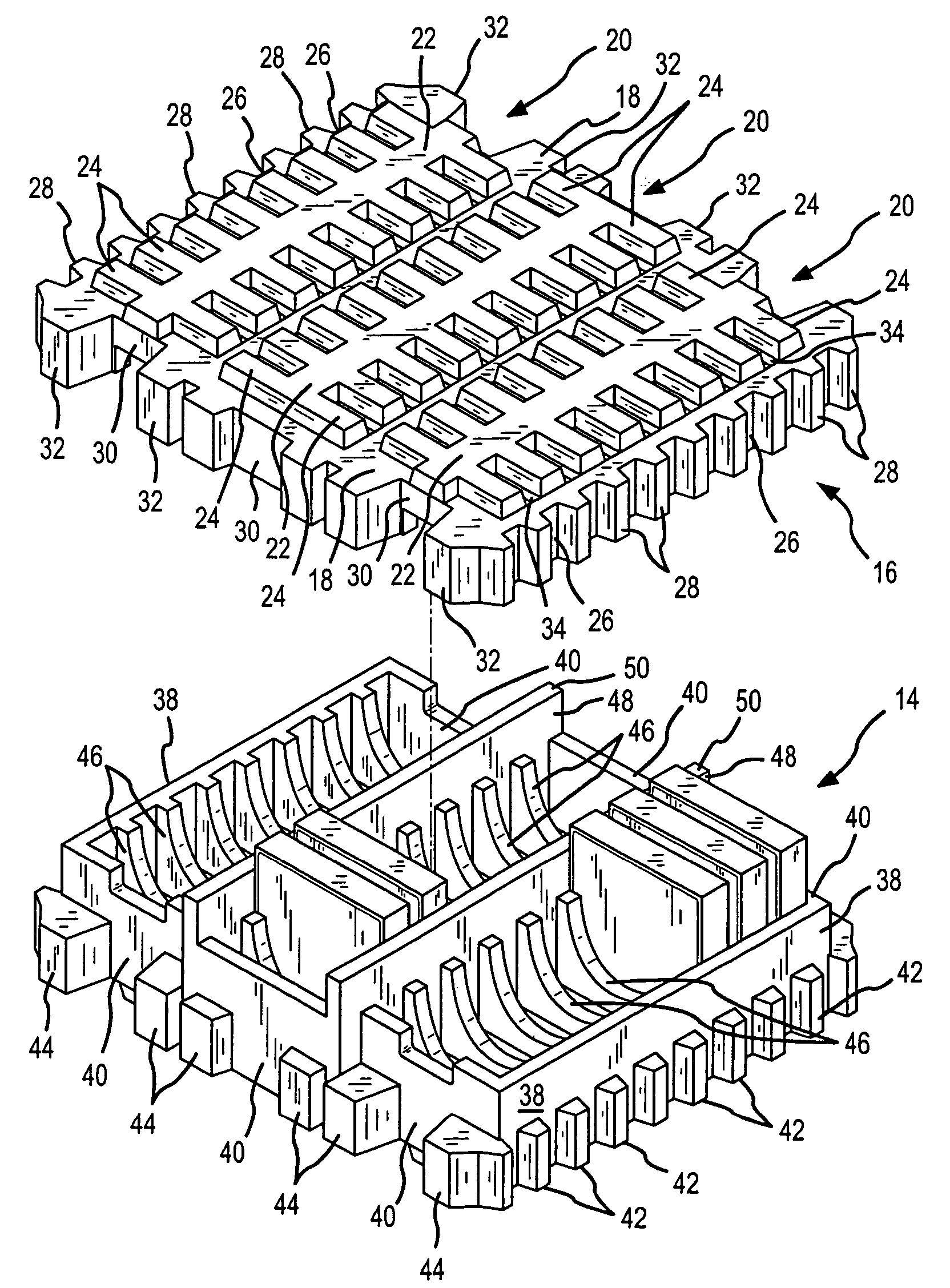
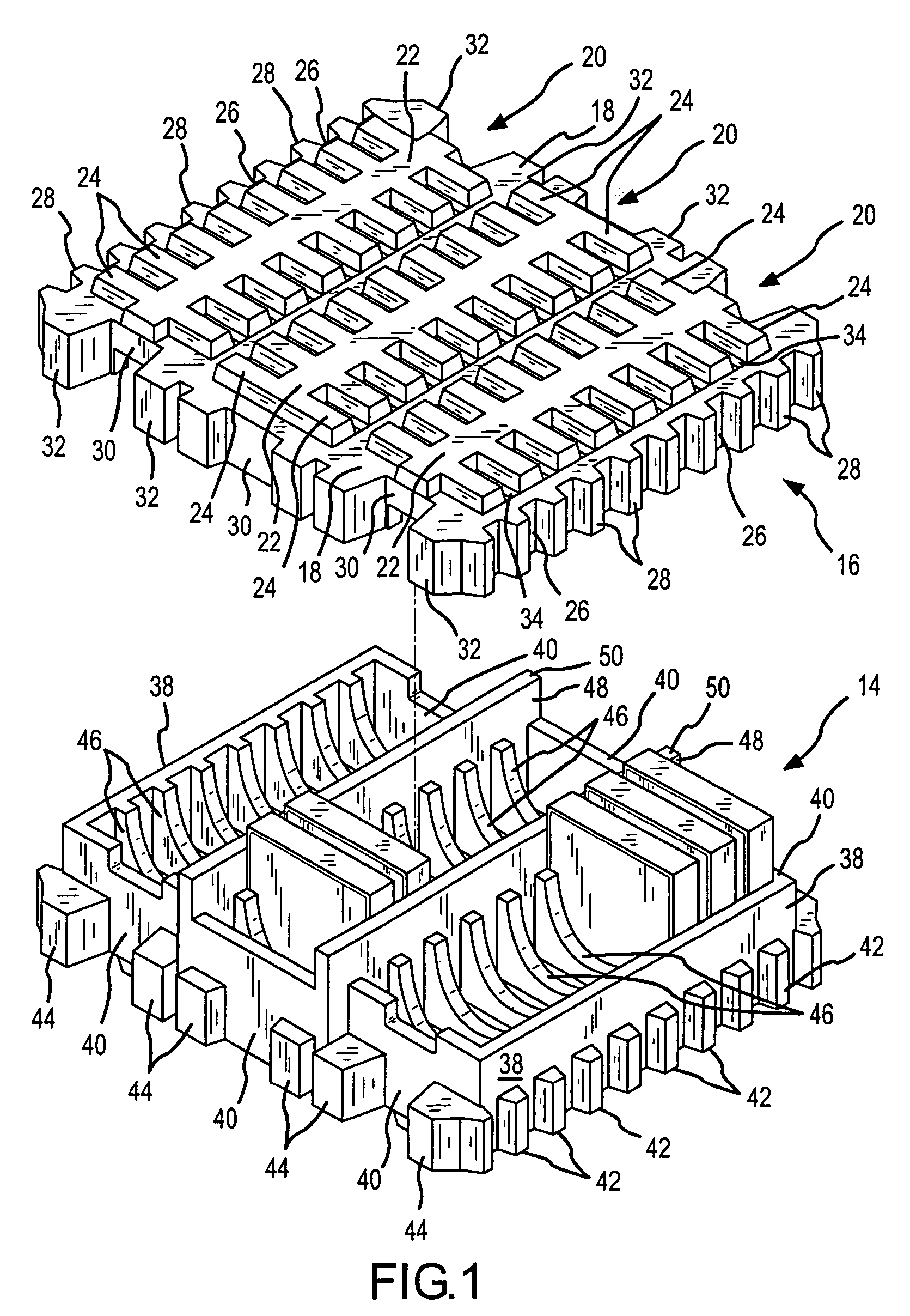
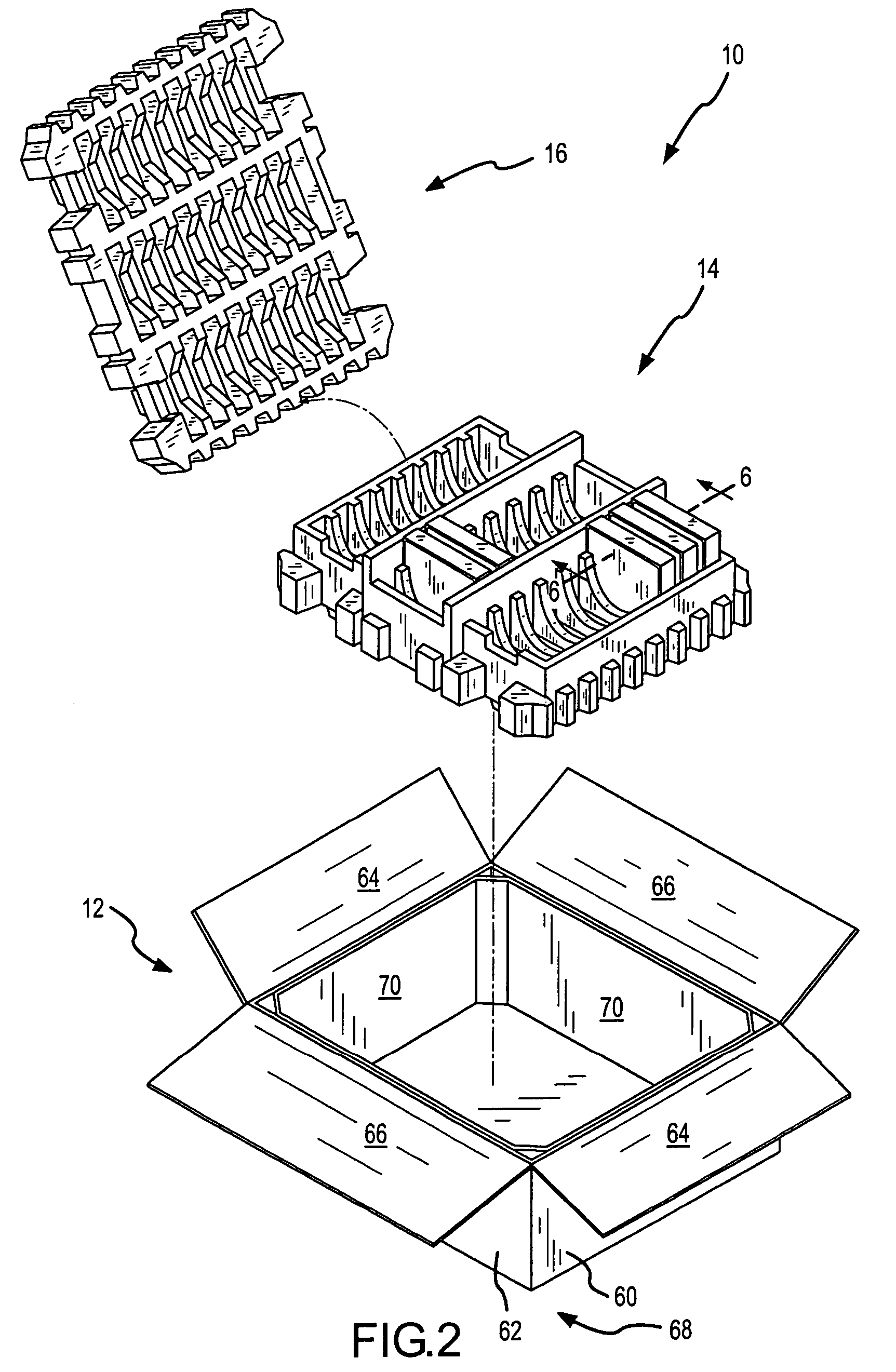
[0023]FIGS. 1 and 2 illustrate the container 10 of the present invention. As shown, the container 10 includes three major components, namely, a cardboard or corrugated shell 12, a main or first insert 14, and a second insert or top cover 16. A few disk drives D are shown mounted in the main insert.

[0024]Beginning first with a description of the top cover 16, and also referring to FIGS. 3 and 4, this component is characterized by a planar base surface 18 that extends around a periphery or perimeter of the top cover, and extends continuously between rows 20 of cushioning ribs. Each row of cushioning ribs 20 includes a plurality of individual cushioning ribs 24 arranged in opposing pairs. Ribs 24 are spaced from one another by recesses 34 that are formed on the upper planar surface 18. The recesses 34 extend below the planar base surface 18. A central support beam 22 interconnects pairs of cushioning ribs 24, and the beam 22 extends substantially perpendicular to the pairs of cushionin...


PUM


Abstract

A shipping container includes a main insert, a top cover and a cardboard or corrugated shell. The container is especially adapted for securing computer disk drives therein. Potential damage to the disk drives is minimized by isolating movement of the disk drives within the container. Each drive is loaded within a compartment defined by surrounding dividers formed on both the top cover and main insert. The overall container height is minimized by incorporating recesses in the inserts that can increase the effective height of exterior cushioning ribs thus reducing the thickness of the floorboard or base member. The incorporation of the recesses results in formation of relatively thin web sections that interconnect base portions of the cushioning ribs to base portions of the dividers.

Description

CROSS REFERENCE TO RELATED APPLICATION[0001]Priority is claimed from U.S. Provisional Patent Application Ser. No. 60 / 617,153, filed on Oct. 8, 2004, entitled “Active Beam Shock Protection Package for Multi Disk Drive Shipment” the disclosure of which is incorporated herein by reference in its entirety.FIELD OF THE INVENTION[0002]The present invention relates to a container or package used for shipment and storage of objects therein, and more particularly, to a container or package especially adapted for shipment and storage of computer disk drives wherein the container protects the drives from vibration and shock that may occur during shipment and storage, yet the container is minimized in size.BACKGROUND OF THE INVENTION[0003]Computer disk drives are common to personal computers, laptop computers and other computing devices. As with most products, computer disk drives must be shipped from a manufacturer or distributor to another location where the disk drives may be sold or used. A...

Claims


Application Information

Patent Timeline
Patent Type & Authority Patents(United States)
IPC IPC(8): B65D85/30B65D81/02
CPCB65D81/113B65D5/509
Inventor HONG, TERENCE TEN TECKNEWBURN, PAUL
Owner SEAGATE TECH LLC
Why Eureka
Try Eureka