Pipette tip

a pipette and tip technology, applied in the field of pipette tips, can solve the problems of already large force for placement and throwing off, and achieve the effects of facilitating the deformation of the circumferential rib, reducing the thickness of the wall, and softer materials

Inactive Publication Date: 2009-09-08
EPPENDORF AG
View PDF9 Cites 3 Cited by
  • Summary
  • Abstract
  • Description
  • Claims
  • Application Information

AI Technical Summary

Benefits of technology

[0012]When thrown off, the throw-off device of the pipetting device presses at the upper end of the pipette tip against the at least one further rib. By the at least one further rib the throw-off force is transmitted to at least one position of the circumferential rib at a maximum distance from the lower end. As a result this at least one position of the circumferential rib is pressed slightly toward the lower end. Relative to a plane positioned at right angles to the tubular body of the pipette tip, the circumferential rib is pressed slightly flatter. The at least one further rib forms a rigid region which when forces are transmitted is subjected to only relatively small deformations. As the circumferential rib is positioned transversely to the at least one further rib, it is relatively easily deformable by the forces introduced in the direction of the further rib. As a result the circumferential rib flares slightly and the static friction between the inner face of the circumferential rib or the contact region and the receiving shank is correspondingly reduced. Thus the throw-off forces required to release the pipette tip from the receiving shank are reduced. Moreover the pipette tip is more flexible in the region of the circumferential rib, so that the forces for placement on a receiving shank are also reduced and placement on receiving shanks of different dimensions is facilitated.
[0013]The curve along which the circumferential rib extends can have different geometries. According to an embodiment the circumferential rib has a path corresponding to a sine curve or a rectangular curve or a triangular curve or a sawtooth curve or a further periodic curve. The rectangular curve, triangular curve or sawtooth curve or other curves comprising principal corners can also be rounded off at the corners. The circumferential rib extends over one or more periods on the periphery. When extended over a plurality of periods the circumferential rib comprises a plurality of positions at a maximum distance from the lower end, in which the throw-off force can be introduced symmetrically into the circumferential rib via a plurality of further ribs. As a result the throw-off force is particularly advantageously reduced and the flexibility increased.
[0023]According to an embodiment, in a flexible axial region adjacent to the circumferential rib on the face facing the lower end the body has a smaller wall thickness and / or a softer material than in a region closer to the lower end. The flexible axial region facilitates the deformation of the circumferential rib by the throw-off forces introduced via the at least one further rib and the flexibility in the sealing region.
[0024]According to an embodiment, between the circumferential rib and the at least one further rib and optionally the further circumferential rib the body has no wall or a smaller wall thickness and / or a softer material than between the lower end and the circumferential rib or the flexible axial region. As a result the force transmission from the upper end is facilitated via the at least one further rib and the throwing-off facilitated and the flexibility improved.
[0026]Finally, according to an embodiment the pipette tip is manufactured integrally from at least one plastic material. The pipette tip can advantageously be manufactured from a single plastic material, the flexibility in the upper region being improved by wall thickening / thinning or perforations. Furthermore the pipette tip can advantageously be manufactured by multi component injection moulding from a plurality of different plastics of varying rigidity or softness.

Problems solved by technology

As a result, the forces for placement and throwing off are already much too large.

Method used


Image

  • Pipette tip
  • Pipette tip
  • Pipette tip

Examples


Embodiment Construction

[0028]While this invention may be embodied in many different forms, there are described in detail herein a specific preferred embodiment of the invention. This description is an exemplification of the principles of the invention and is not intended to limit the invention to the particular embodiment illustrated

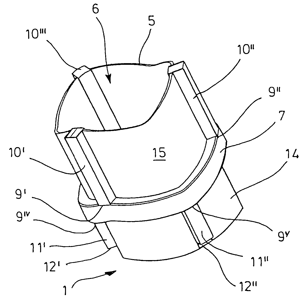
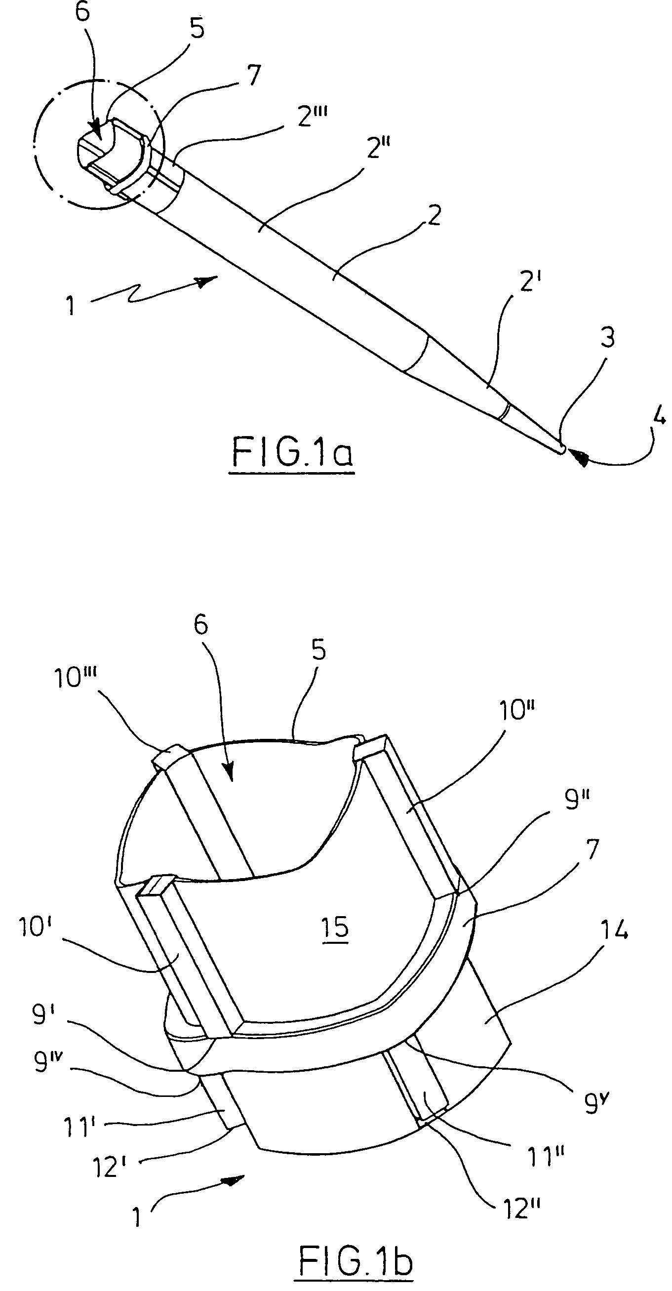
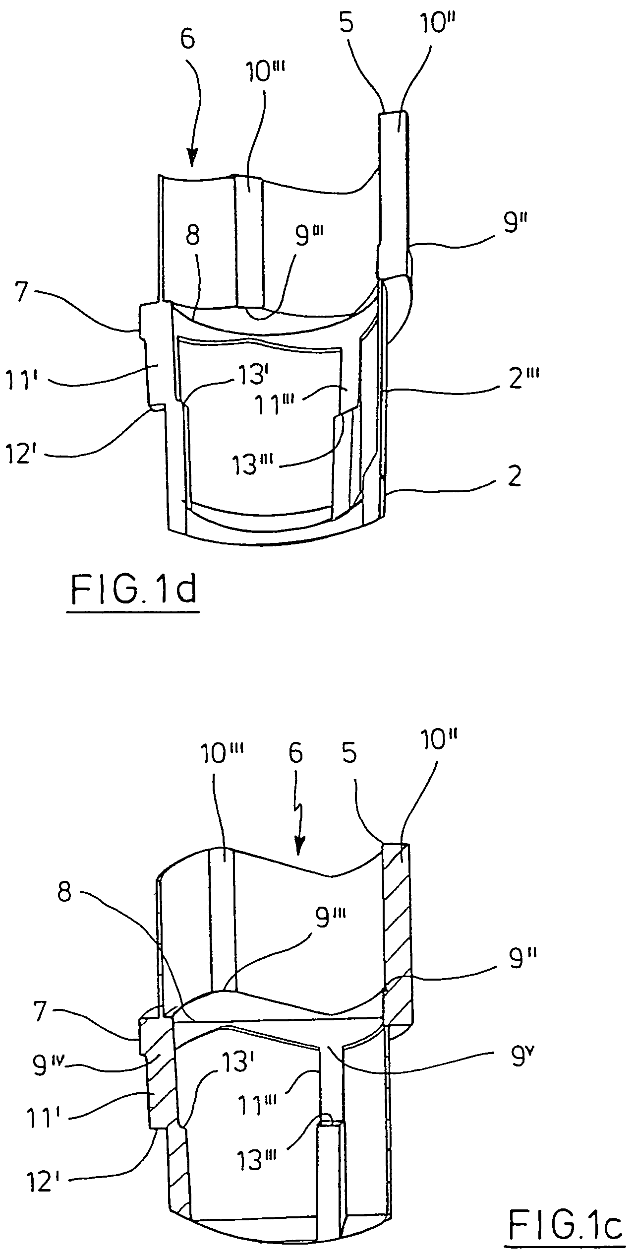
[0029]FIGS. 1a to d show a pipette tip with wave-shaped circumferential rib and further ribs parallel to the axis in a perspective side view (FIG. 1a), in an enlarged detail of the upper end from the same perspective (FIG. 1b), in an enlarged longitudinal section through the upper end (FIG. 1c) and in the same section in a further perspective (FIG. 1d);

[0030]FIGS. 2a and b show a pipette tip with a further circumferential rib at the upper end in a longitudinal section through the upper end (FIG. 2a) and in the same longitudinal section in a further perspective (FIG. 2b);

[0031]FIGS. 3a and b show a pipette tip with further ribs oriented obliquely and connected to one another on...


PUM

PropertyMeasurementUnit
distanceaaaaaaaaaa
thicknessaaaaaaaaaa
forceaaaaaaaaaa

Abstract

Pipette tip made from plastics with an elongate, tubular body which comprises at a lower end a pipetting aperture, at an upper end a placement aperture (6) for placement on a receiving shank of a pipetting device, in the vicinity of the upper end a circumferential rib along a closed curve comprising different spacings from the lower end in different contour positions, a circumferential contact region on a surface of revolution on the inner face of the circumferential rib and at least one further rib extended from at least one position of the circumferential rib at a maximum distance from the lower end as far as the upper end.

Description

CROSS-REFERENCE TO RELATED APPLICATIONS[0001]Not applicable.STATEMENT REGARDING FEDERALLY SPONSORED RESEARCH[0002]Not applicable.BACKGROUND OF THE INVENTION[0003]Pipette tips are used together with pipetting devices for metering liquids. Pipette tips have an elongate, tubular body which has a pipetting aperture at the lower end and a placement aperture at the upper end for placement on a receiving shank of the pipetting device. The receiving shank is typically of conical shape. However cylindrical receiving shanks or a mixture of forms are also known. Furthermore there are conical or cylindrical receiving shanks which have circumferential bulges or the like to intensify the sealing or clamping action. The pipetting device comprises a gas displacement device, which typically is designed as a piston-and-cylinder unit. The gas displacement device is connected to a through-aperture of the receiving shank. The pipette tip is fixed by forcing the receiving shank of the pipetting device in...

Claims


Application Information

Patent Timeline
Patent Type & Authority Patents(United States)
IPC IPC(8): B01L3/02B29C45/37G01N1/00B29L23/00G01N35/10
CPCB01L3/0279G01N2035/103B01L2300/0858B01L2200/0689
Inventor LOHN, JURGEN
Owner EPPENDORF AG
Why Eureka
Try Eureka