Redundant electrical brake and protection system for electric generators

a protection system and electric generator technology, applied in the direction of electric generator control, process and machine control, instruments, etc., can solve the problems of loss of production, large mechanical brakes, and large force exerted by the wind turbine stopper, so as to achieve energy dissipation, dissipate energy, and dissipate energy from the electric generator

Active Publication Date: 2009-09-08
GE INFRASTRUCTURE TECH INT LLC
View PDF9 Cites 39 Cited by
  • Summary
  • Abstract
  • Description
  • Claims
  • Application Information

AI Technical Summary

Problems solved by technology

For example, in instances where high winds prevail, stopping the wind turbine could exert unreasonable or excessive forces upon the components of the wind turbine.
However, mechanical brakes can be large, expensive and wear quickly if the braking event occurs often.
Such systems require periodic maintenance and testing to ensure reliability, and this causes at least some loss in production.
Typically, the mechanical brake has a relatively long response time (tens of seconds).
Under some severe conditions, the long response time can result in over-speed of the electric generator.
Controlling the de-energization process using mechanical brakes is difficult.
Further, such systems must be fail-safe and meet high reliability standards.

Method used


Image

  • Redundant electrical brake and protection system for electric generators
  • Redundant electrical brake and protection system for electric generators
  • Redundant electrical brake and protection system for electric generators

Examples


Embodiment Construction

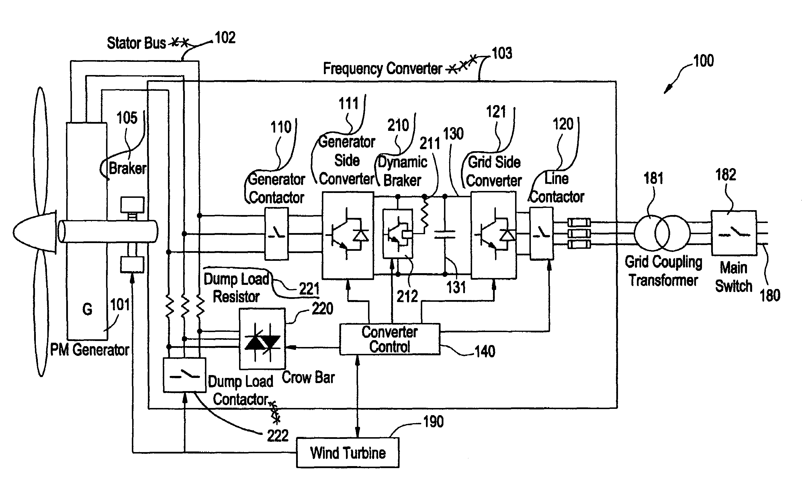
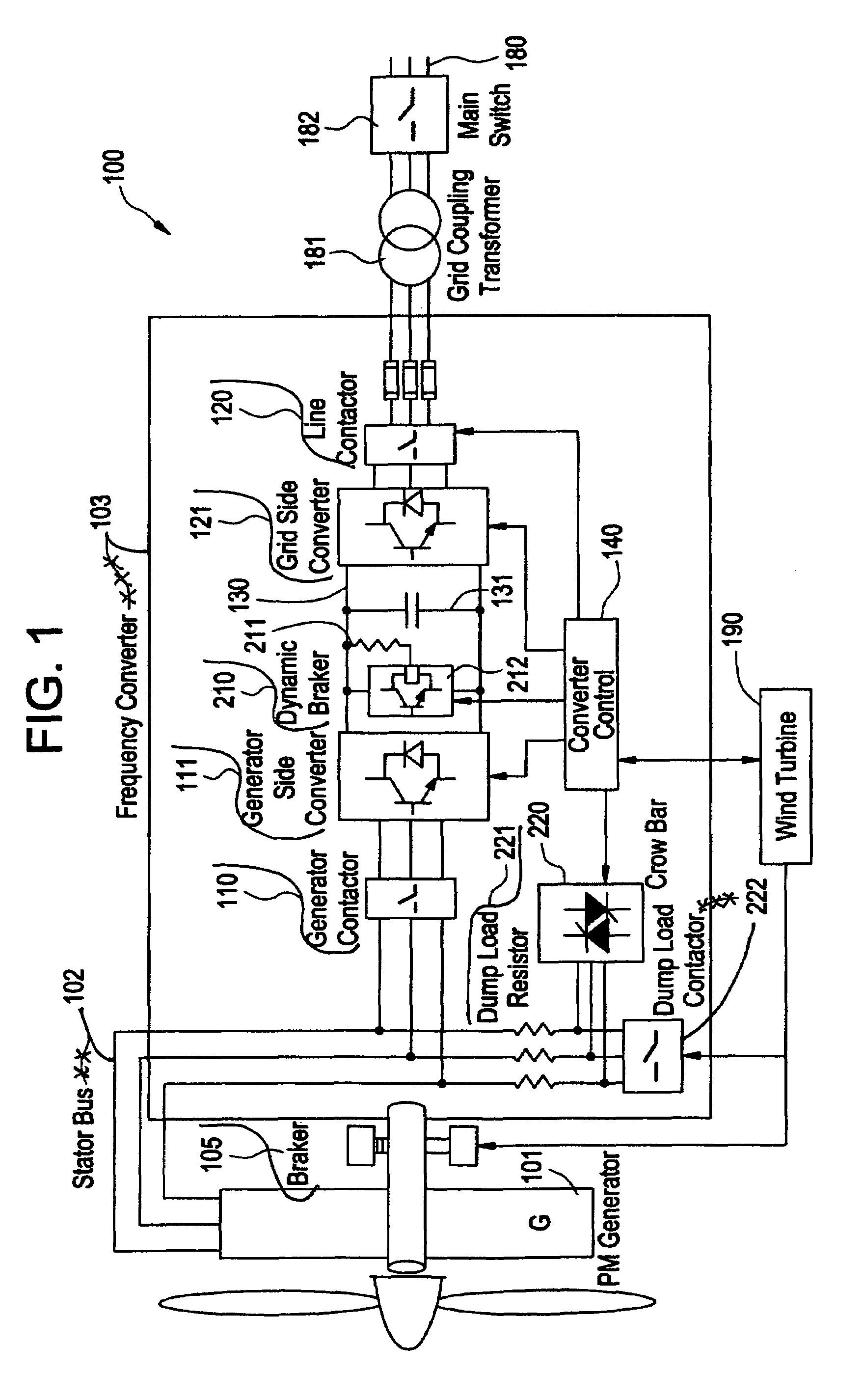
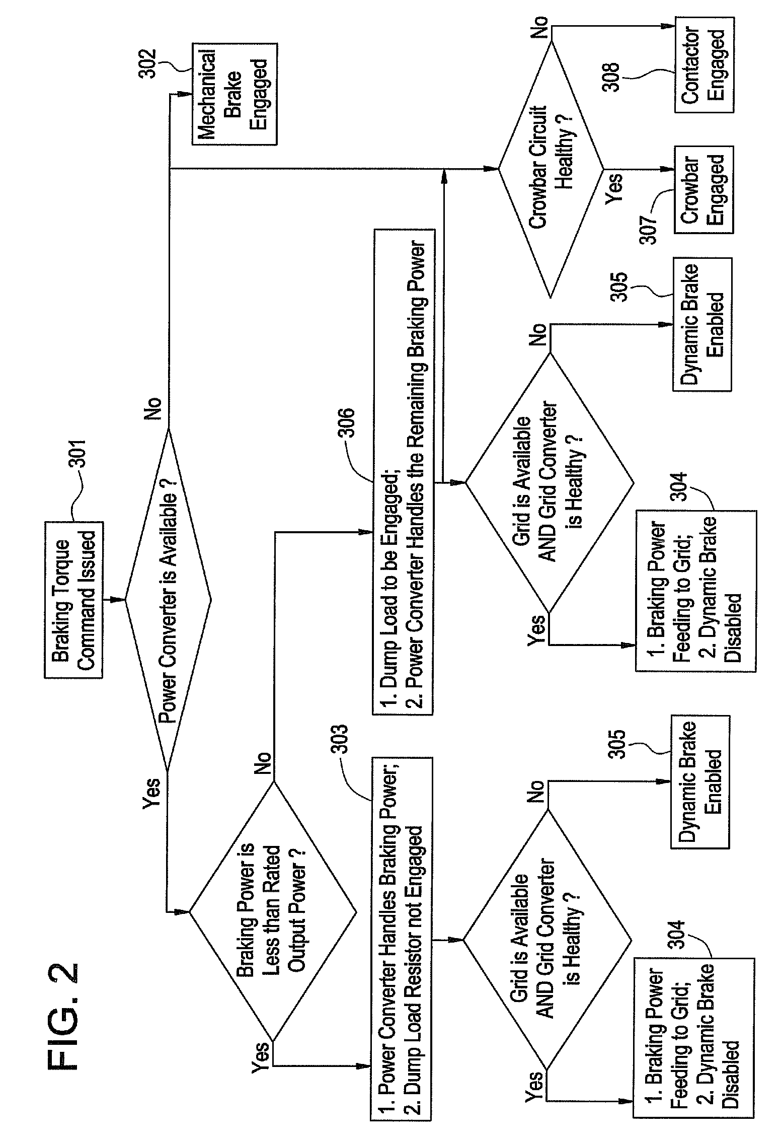
[0014]The teachings herein provide for a redundant protection system having a dynamic brake and a crowbar circuit for effective de-energizing of an electric generator.

[0015]As used herein, the terms “disturbance,”“grid disturbance,”“fault,”“system fault,”“transient” and other similar terminology generally refers to any event causing perturbations in a signal of an electric grid to which the electric generator is electrically connected. Examples of events that may cause a disturbance in the grid signal (e.g., a fault on an electric grid) are well known and not discussed further herein. Inevitably, as a variety of generating facilities contribute to the grid signal and as a variety of phenomena including transient events may occur, the components of the grid signal may degrade or vary to some extent. A tolerance for signal perturbation is typically selected by the system operator when opting for automatic response of the electrical brake and protection system.

[0016]As discussed herein...


PUM


Abstract

An apparatus for electric braking and system protection for an electric generator includes a dynamic brake and a crowbar circuit designed for cooperation with power converters to dump power upon command. The dynamic brake includes at least one resistor and the crowbar circuit includes another at least one resistor for dissipating power from the electric generator. Methods for use of the electric braking and system protection calls for shunting the power to at least one of the dynamic brake, the crowbar circuit and the generator side power converter.

Description

BACKGROUND OF THE INVENTION[0001]The teachings herein relate generally to techniques for safe and controllable de-energizing of an electrical generator. In this context, de-energizing of an electrical generator pertains to countering the motive forces on the generator shaft, the reduction of rotational energy stored in the rotational mass of the generator, and the reduction of electromagnetic field energy stored in the generator.[0002]In embodiments where control over the motive force is limited or not possible, methods for de-energization of the generator in a controlled manner must be provided. One example includes generators driven by a wind turbine. For example, in instances where high winds prevail, stopping the wind turbine could exert unreasonable or excessive forces upon the components of the wind turbine.[0003]Some attempts to provide for effective de-energization have employed mechanical brakes. However, mechanical brakes can be large, expensive and wear quickly if the bra...

Claims


Application Information

Patent Timeline
Patent Type & Authority Patents(United States)
IPC IPC(8): H02P13/00
CPCF03D7/0248F03D7/0272F03D9/003H02P3/22H02P3/26H02P9/08H02P1/52H02P9/10H02P9/105Y02E10/725Y10S388/92Y02E10/723F03D9/255Y02E10/72Y02P80/10
Inventor LI, LEILU, ZHIGANGTEICHMANN, RALPHWANG, CHANGYONGYANG, WENQIANG
Owner GE INFRASTRUCTURE TECH INT LLC
Why Eureka
Try Eureka