
Operational time extension

a technology of time extension and operation, which is applied in the direction of logic circuits, pulse techniques, instruments using specific components, etc., can solve the problems that have not yet been fully developed, and achieve the effect of reducing signal delay

Inactive Publication Date: 2009-09-08
ALTERA CORP
View PDF206 Cites 50 Cited by
  • Summary
  • Abstract
  • Description
  • Claims
  • Application Information

AI Technical Summary

Benefits of technology

This approach enables efficient signal propagation by maintaining configurations over multiple cycles, optimizing signal delay, and satisfying timing constraints, thereby enhancing the operational efficiency of reconfigurable ICs.

Problems solved by technology

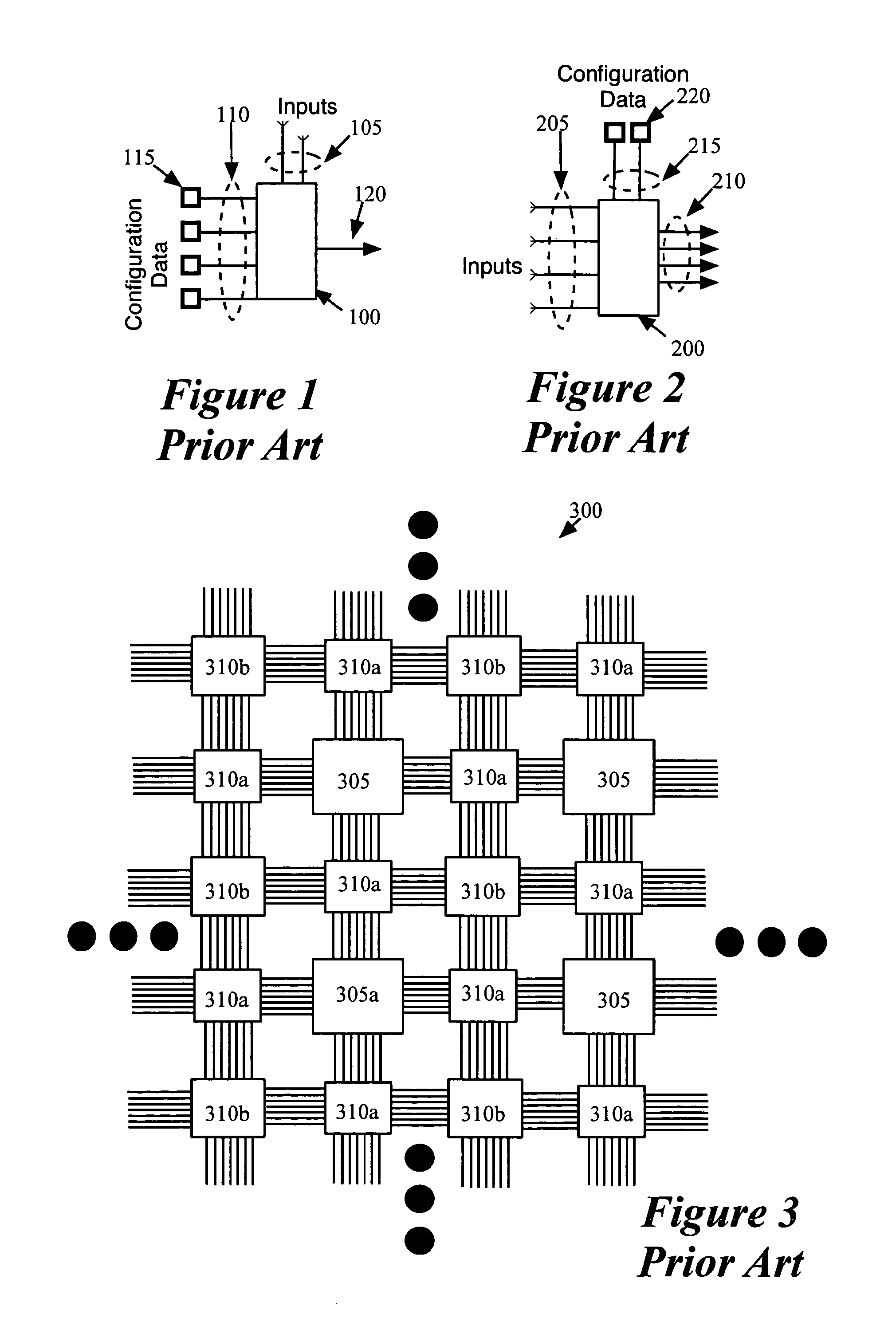
One area of this technology that has not yet been fully developed is how to assign different operations that the reconfigurable IC performs to different configuration periods during runtime.

Method used


Image

  • Operational time extension
  • Operational time extension
  • Operational time extension

Examples


Embodiment Construction

[0048]In the following description, numerous details are set forth for purpose of explanation. However, one of ordinary skill in the art will realize that the invention may be practiced without the use of these specific details. For instance, not all embodiments of the invention need to be practiced with the specific number of bits and / or specific devices (e.g., multiplexers) referred to below. In other instances, well-known structures and devices are shown in block diagram form in order not to obscure the description of the invention with unnecessary detail.

[0049]For an IC that has several operational cycles, some embodiments of the invention provide a method that assigns the components in an IC design to different configurable circuits and different operational cycles of the IC. In some embodiments, this method is an optimization process that concurrently optimizes the assignment of the IC-design components to different configurable circuits and different operational cycles of the...


PUM


Abstract

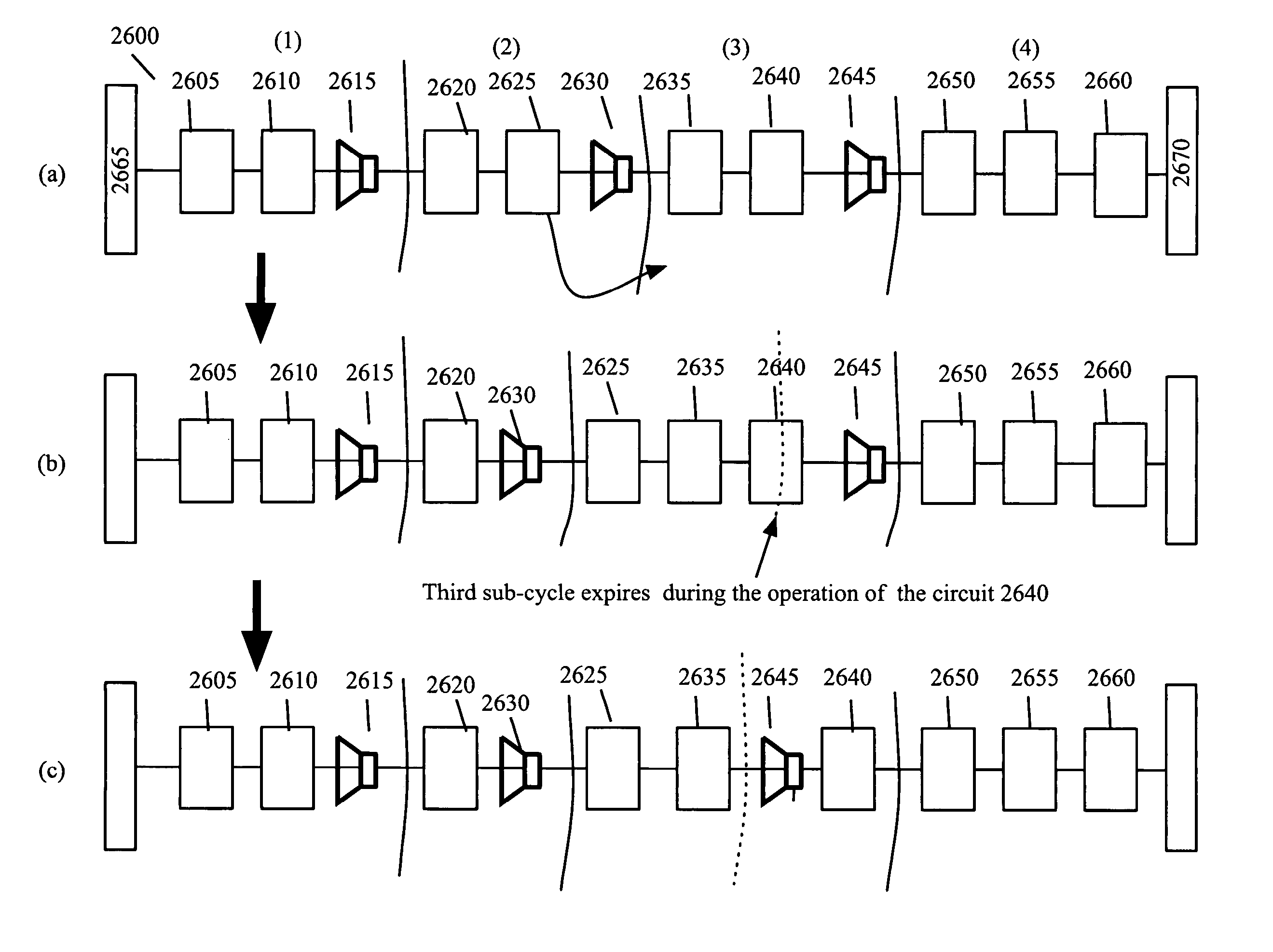
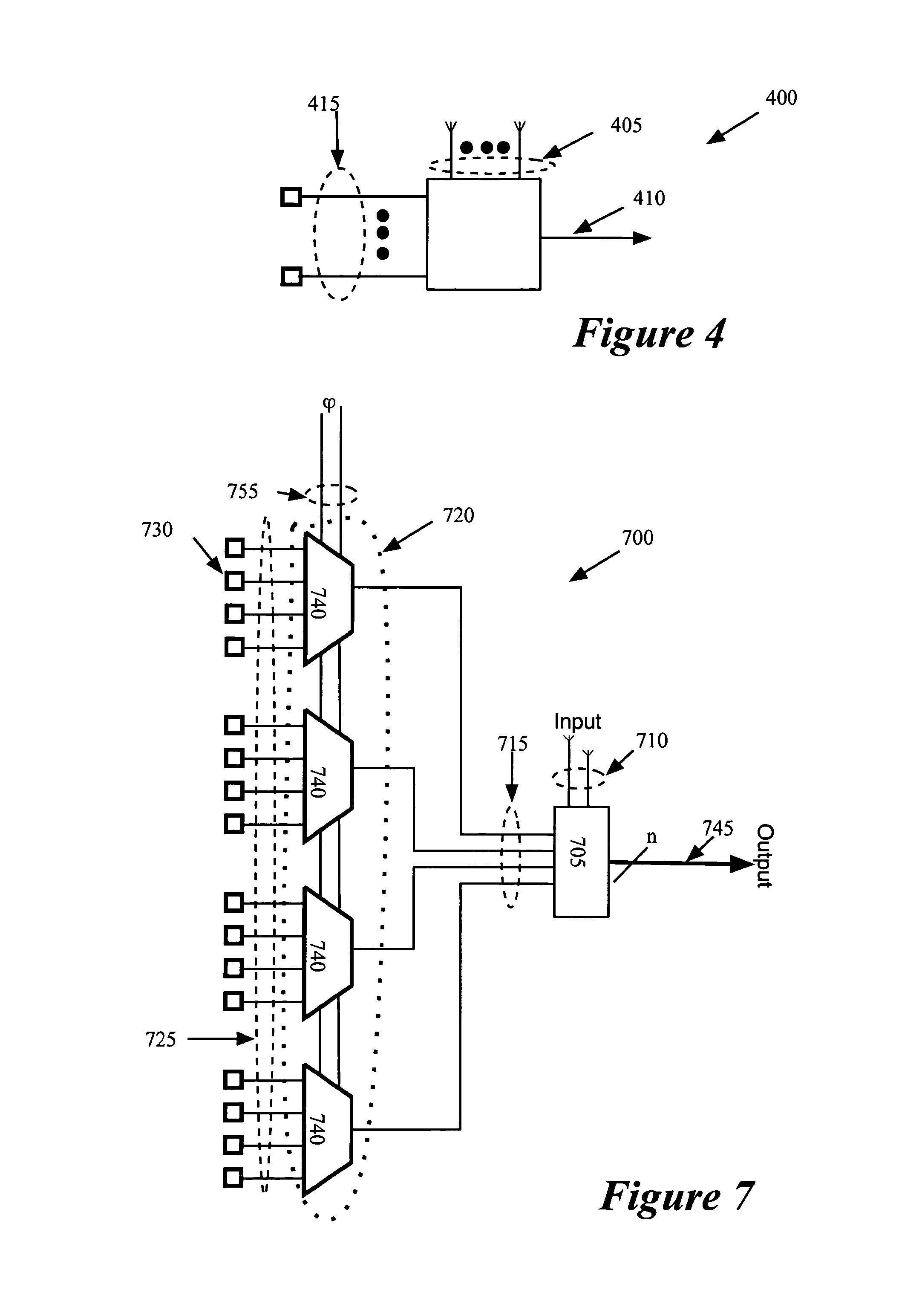
Some embodiments provide a reconfigurable integrated circuit (“IC”). This IC has several reconfigurable circuits, each having several configurations for several configuration cycles. The reconfigurable circuits include several time-extending reconfigurable circuits. During the operation of the IC, each particular time-extending reconfigurable circuit maintains at least one of its configurations over at least two contiguous cycles, in order to allow a signal to propagate through a signal path, which contains the particular time-extending circuit, within a desired amount of time.

Description

CLAIM OF BENEFIT TO PRIOR APPLICATION[0001]This application is a continuation application of U.S. patent application Ser. No. 11 / 082,200 filed Mar. 15, 2005, now U.S. Pat. No. 7,236,009 entitled “Operational Time Extension”, which is incorporated herein by reference. U.S. patent application Ser. No. 11 / 082,200 claims benefit to U.S. Provisional Patent Application 60 / 632,277 filed Dec. 1, 2004, entitled “Method and Apparatus for Sub-Cycle Assignment for a Reconfigurable IC”.CROSS REFERENCE TO RELATED APPLICATIONS[0002]This Application is related to the following applications: U.S. patent application Ser. No. 11 / 081,823, filed Mar. 15, 2005; U.S. patent application Ser. No. 11 / 081,854, filed Mar. 15, 2005, now issued as U.S. Pat. No. 7,428,721; U.S. patent application Ser. No. 12 / 193,712, filed Aug. 18, 2008; U.S. patent application Ser. No. 12 / 193,713, filed Aug. 18, 2008; and U.S. patent application Ser. No. 12 / 193,707, filed Aug. 18, 2008.FIELD OF THE INVENTION[0003]The present inv...

Claims


Application Information

Patent Timeline
Patent Type & Authority Patents(United States)
IPC IPC(8): G06F17/50H03K19/00H03K19/177
CPCG06F17/5054H03K19/17736H03K19/173H03K19/17756H03K19/17776H03K19/17752H03K19/17758G06F30/34G06F30/394G06F30/347
Inventor ROHE, ANDRETEIG, STEVENSCHMIT, HERMANREDGRAVE, JASONCALDWELL, ANDREW
Owner ALTERA CORP
Learn More