Semiconductor device and chip-stack semiconductor device

a semiconductor device and semiconductor technology, applied in semiconductor devices, semiconductor/solid-state device details, electrical apparatus, etc., can solve problems such as heat, delay signals, and difficulties in reducing the thickness of csp semiconductor devices, and achieve the effects of preventing the resistance of electrodes from excessive voltage drop, delay, and loss

Inactive Publication Date: 2006-10-19
SAMSUNG ELECTRONICS CO LTD
View PDF11 Cites 28 Cited by
  • Summary
  • Abstract
  • Description
  • Claims
  • Application Information

AI Technical Summary

Benefits of technology

[0016] The present invention has an objective to offer a semiconductor device and a chip-stack semiconductor device which are capable of preventing the electrodes' resistance from developing excessive voltage drop, heat, delay, and loss and also from varying from one electrode to the other.
[0018] According to the invention, the multiple through electrodes have mutually differing cross-sectional areas; increasing the cross-sectional areas of the through electrodes for terminals required to conduct large electric current reduces the resistance of the through electrodes and alleviates heating, signal delay, etc.
[0019] Therefore, a semiconductor device can be provided which is capable of preventing the resistance of the through electrodes from developing excessive voltage drop, heat, delay, and loss, and also from varying from one electrode to the other.
[0021] According to the invention, the above-described semiconductor chips are stacked on top of each other. The area of the through electrodes required to make interconnects over an extended length can be increased in accordance with that length. This reduces the resistance of the electrodes and alleviates voltage drop, heat, delay, and loss. Variations in resistance between terminals can also be reduced.
[0022] In addition, designating some of the through electrodes as non-contact through electrodes not electrically connected to the semiconductor chips allows a current to flow all the way from the top chip to the bottom chip.

Problems solved by technology

These factors present difficulties in reducing the thickness of the CSP semiconductor device 100.
This raises problems that those terminals which need pass great electric current may heat up, delay signals, or develop other undesirable phenomena.
The extra length of the electrode translates into an extra resistance, resulting in voltage drop, heating, delay, and loss.

Method used


Image

  • Semiconductor device and chip-stack semiconductor device
  • Semiconductor device and chip-stack semiconductor device
  • Semiconductor device and chip-stack semiconductor device

Examples


embodiment 1

[0037] Referring to FIG. 1 through FIG. 8, the following will describe an embodiment according to the present invention.

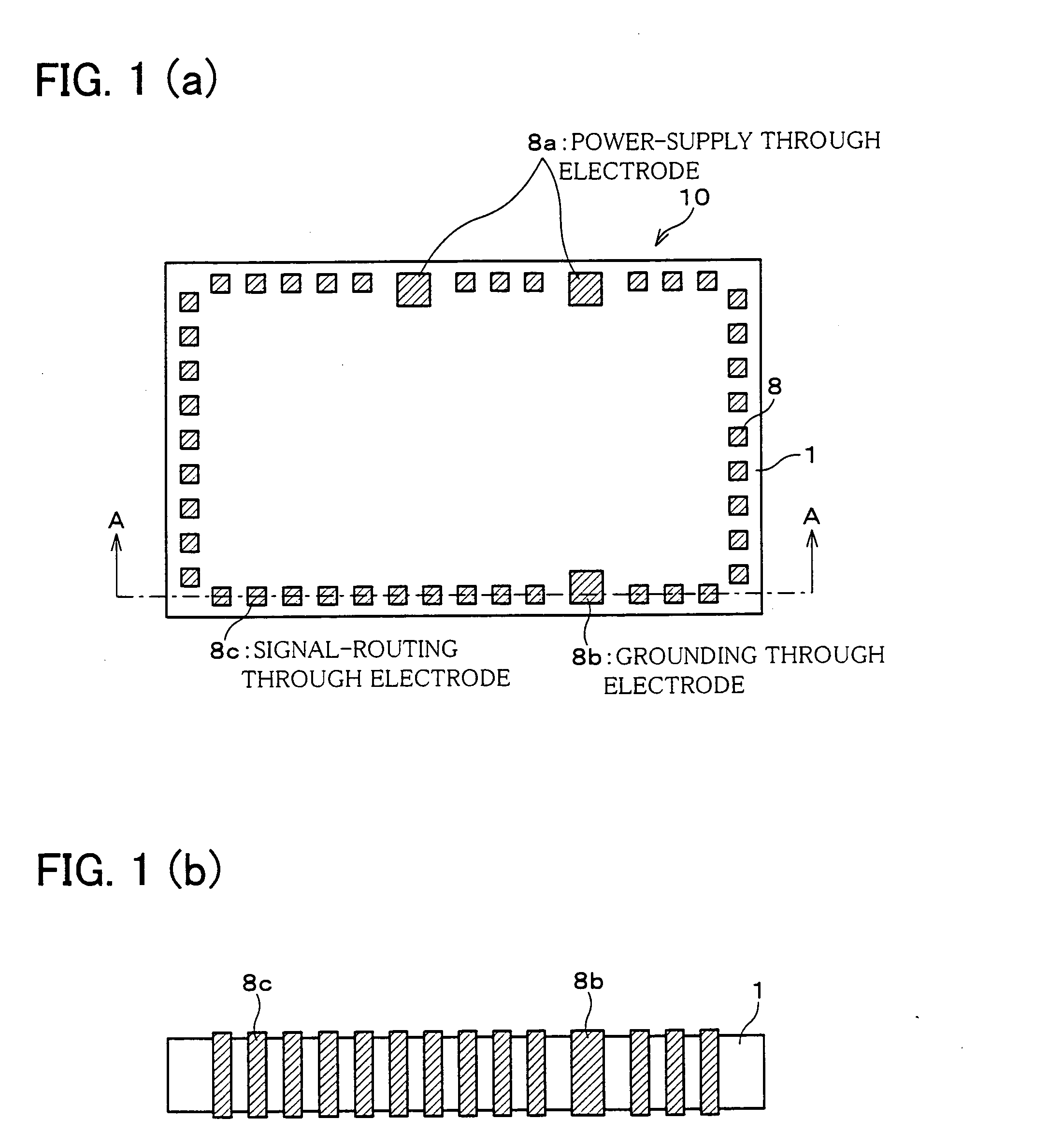
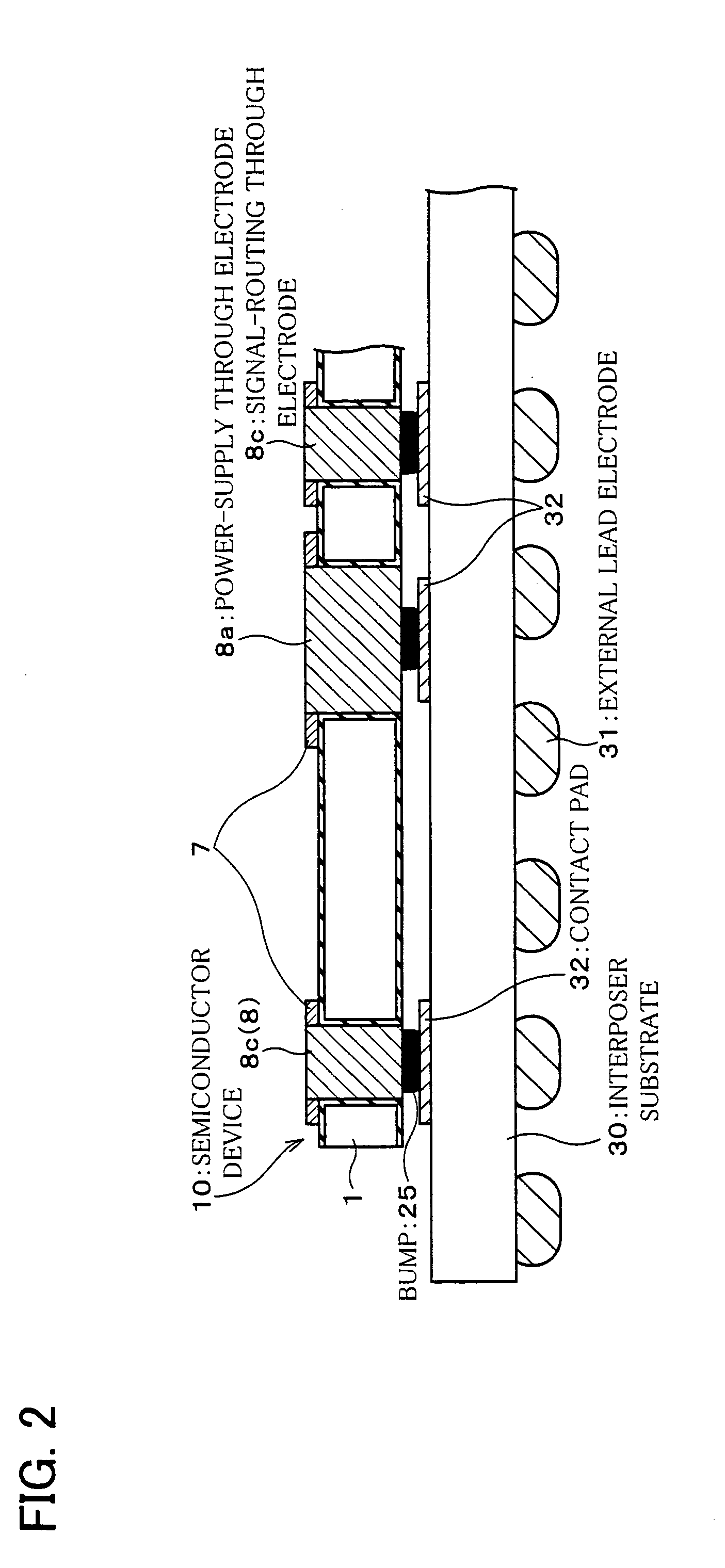
[0038]FIG. 1(a) is a plan view illustrating a semiconductor device 10 in the present embodiment. A semiconductor chip 1 in the semiconductor device 10 has along its periphery multiple through electrodes 8 having differing cross-sectional areas. The through electrodes 8 are made through the semiconductor chip 1.

[0039] As shown in FIGS. 1(a), 1(b), the through electrodes 8 are divided into three major types: power-supply through electrodes 8a, grounding through electrodes 8b, and signal-routing through electrodes 8c. The power-supply through electrode 8a and the grounding through electrode 8b have a different cross-sectional area from that of the signal-routing through electrode 8c. More specifically, the power-supply through electrode 8a and the grounding through electrode 8b have a greater cross-sectional area than the signal-routing through electrode 8c.

[0040] ...

embodiment 2

[0086] The following will describe another embodiment of the present invention with reference to FIG. 9. For convenience, members of the present embodiment that have the same arrangement and function as members of embodiment 1, and that are mentioned in that embodiment are indicated by the same reference numerals and description thereof is omitted.

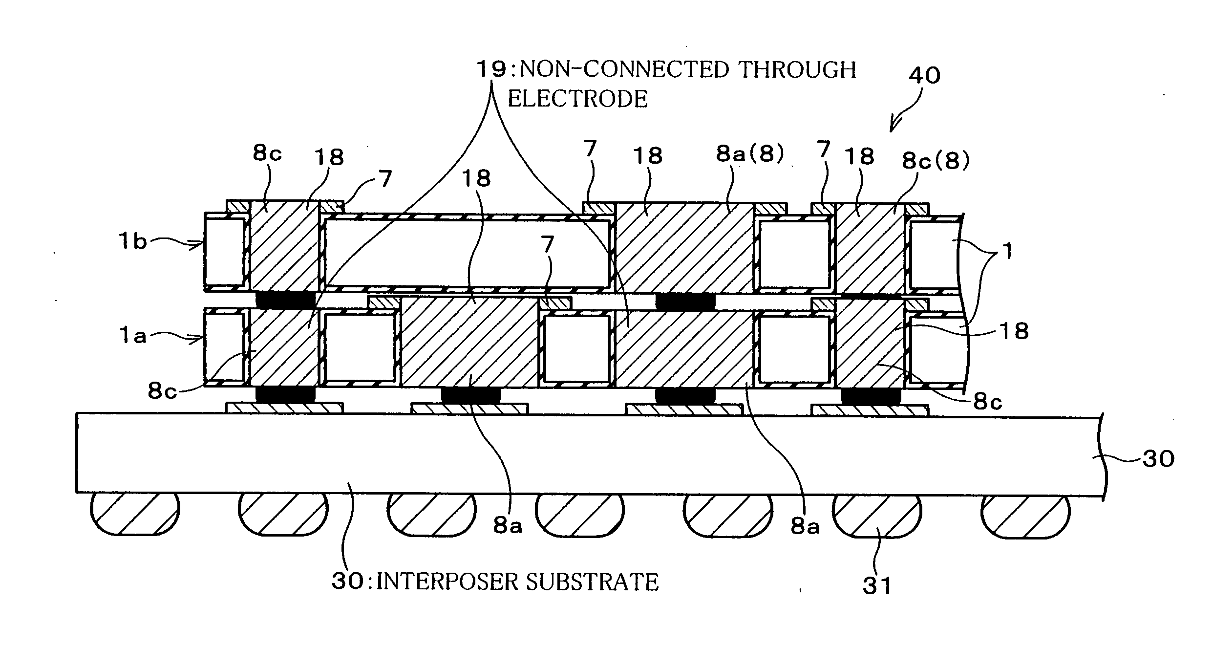
[0087] The present embodiment will describe a chip-stack semiconductor device which includes multiple in general and two in particular stacked semiconductor chips of the semiconductor device 10 of embodiment 1.

[0088] Referring to FIG. 9, the chip-stack semiconductor device 40 of the present embodiment includes an interposer substrate 30 on which are sequentially stacked two semiconductor chips 1: a semiconductor chip 1a and a semiconductor chip 1b. In an example of this kind of chip-stack semiconductor device 40, the semiconductor chip 1a is a logic memory, and the semiconductor chip 1b is a flash memory.

[0089] In the chip-stack semicon...

embodiment 3

[0106] The following will describe another embodiment of the present invention with reference to FIG. 10. For convenience, members of the present embodiment that have the same arrangement and function as members of embodiments 1, 2, and that are mentioned in that embodiment are indicated by the same reference numerals and description thereof is omitted.

[0107] The present embodiment will describe a chip-stack semiconductor device which includes multiple in general and five in particular semiconductor chips 1 of embodiment 1 stacked on top of each other.

[0108] Referring to FIG. 10, a chip-stack semiconductor device 50 of the present embodiment includes an interposer substrate 30 on which are sequentially stacked five semiconductor chips 1: a first semiconductor chip 1a, a second semiconductor chip 1b, a third semiconductor chip 1c, a fourth semiconductor chip1d, and a fifth semiconductor chip 1e.

[0109] The figure shows that interconnect lines are longer from the uppermost, fifth se...


PUM


Abstract

A semiconductor device has multiple power-supply through electrodes, grounding through electrodes, and signal-routing through electrodes made through a semiconductor chip. The power-supply through electrodes, the grounding through electrodes, and the signal-routing through electrodes differ mutually in cross-sectional area. Hence, a semiconductor device and a chip-stack semiconductor device are provided which are capable of preventing the electrodes' resistance from developing excessive voltage drop, heat, delay, and loss, and also from varying from one electrode to the other.

Description

FIELD OF THE INVENTION [0001] The present invention relates to semiconductor devices including a chip with through electrodes and also to chip-stack semiconductor devices incorporating such semiconductor chips vertically stacked on top of each other, for improved functionality, compactness, and reduced thickness. BACKGROUND OF THE INVENTION [0002] CSP (Chip Size Package) semiconductor devices have been popularly used to meet the demand for compact electronics and automated manufacturing processes. [0003]FIG. 11 shows the cross-sectional structure of a conventional CSP semiconductor device 100 as an example. The CSP semiconductor device 100 has gold wires 103 extending from electrode pads 102 formed along the periphery of a semiconductor chip 101. Through the gold wires 103, the semiconductor chip 101 is electrically connected to an interposer substrate, or circuit board, 104. The CSP semiconductor device 100 has also external lead electrodes 105 formed on the back of the interposer ...

Claims


Application Information

Patent Timeline
Patent Type & Authority Applications(United States)
IPC IPC(8): H01L29/40H01L21/3205H01L23/52H01L21/768H01L23/12H01L23/31H01L23/48H01L25/065H01L25/07H01L25/18
CPCH01L21/76898H01L2224/73204H01L23/481H01L25/0657H01L25/18H01L25/50H01L2224/16145H01L2224/45144H01L2224/48091H01L2224/48227H01L2224/48465H01L2225/06517H01L2225/06541H01L2225/06589H01L2924/01004H01L2924/01013H01L2924/01014H01L2924/01029H01L2924/0105H01L2924/01078H01L2924/01079H01L2924/15311H01L23/3114H01L2224/32225H01L2224/16225H01L24/45H01L24/48H01L2924/0002H01L2224/0401H01L2224/0557H01L2224/02372H01L2224/13025H01L2924/00014H01L2924/00H01L2224/05552H01L2924/181H01L2224/0603H01L2224/05571H01L2224/14H01L2924/00012
Inventor DOTTA, YOSHIHISAKIMURA, TOSHIO
Owner SAMSUNG ELECTRONICS CO LTD
Why Eureka
Try Eureka