Control device of vehicle-onboard electric source

a technology of control device and electric source, which is applied in the direction of battery/fuel cell control arrangement, propulsion by capacitors, instruments, etc., can solve the problems of inability to improve the durability of capacitors, inability to operate properly of capacitors, and difficulty in improving fuel economy. the effect of fuel economy and durability improvemen

Inactive Publication Date: 2013-06-20
MAZDA MOTOR CORP
View PDF24 Cites 1 Cited by
  • Summary
  • Abstract
  • Description
  • Claims
  • Application Information

AI Technical Summary

Benefits of technology

[0006]The present invention has been devised in view of the above-described matters, and an object of the present invention is to provide a co

Problems solved by technology

However, the capacitor's charging with the high voltage quickens the deterioration (decrease of the capacitance, particularly) of the capacitor, compared to the capacitor's charging with a low voltage, so that there is a concern that the capacitor may not function properly until the term of guarantee has expired.
In this case, no improvement o

Method used


Image

  • Control device of vehicle-onboard electric source
  • Control device of vehicle-onboard electric source
  • Control device of vehicle-onboard electric source

Examples


Embodiment Construction

[0018]Hereafter, a preferred embodiment of the present invention will be described specifically referring to the accompanying drawings.

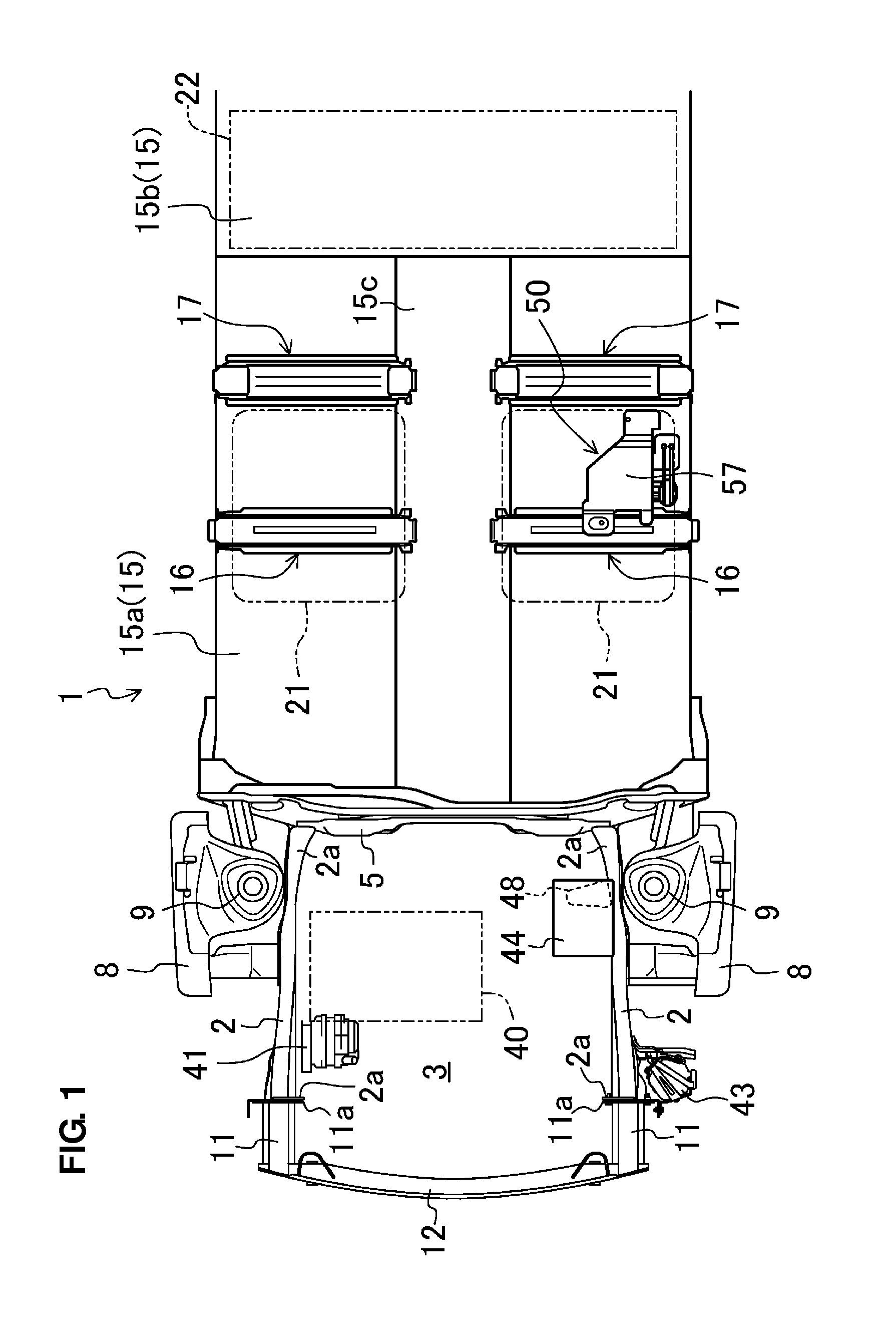
[0019]FIG. 1 shows a structure of a vehicle 1, to which a control device of a vehicle-onboard electric source according to an embodiment of the present invention is installed. The left side in FIG. 1 corresponds to the left side of the vehicle 1. Hereinafter, front, rear, left, right, upper and lower regarding the vehicle 1 will be simply referred to as front, rear, left, right, upper and lower.

[0020]A pair of right-and-left front side frames 2 which extends longitudinally is arranged at both end portions, in a vehicle width direction (a lateral direction), of a front portion of the vehicle 1. A space between the front side frames 2 is an engine room 3 where an engine 40 is provided. A rear portion of each of the front side frames 2 is a kick portion 2a, the level of which lowers gradually toward a rear side. A dash panel 5 which partitions a vehicle...


PUM


Abstract

There are provided a deterioration degree determining module configured to determine whether or not a real-deterioration degree exceeds an estimated-deterioration degree by comparing the real-deterioration degree detected by a real-deterioration degree detecting module and the estimated-deterioration degree memorized by an estimated-deterioration degree memorizing module, and an upper-limit voltage controlling module configured to set an upper-limit voltage of charging of a capacitor by a generator at a limit voltage which is lower than a specified voltage and corresponds to an excess degree of the real-deterioration degree over the estimated-deterioration degree when it is determined that the real-deterioration degree exceeds the estimated-deterioration degree.

Description

BACKGROUND OF THE INVENTION[0001]The present invention relates to a control device of a vehicle-onboard electric source which comprises a generator and a capacitor.[0002]Japanese Patent Laid-Open Publication No. 2010-160091, for example, discloses a working machine with an electromotive machine installed thereto, in which an excess kinetic energy generated by the electromotive machine is converted to an electric energy and stored at a capacitor. This capacitor deteriorates through its long-term use with charging and discharging repeated. Accordingly, this patent publication discloses determination of a deterioration degree of the capacitor by using both the internal resistance and the capacitance of the capacitor in order to improve the accuracy of the determination.[0003]Meanwhile, the fuel economy (gas millage) of a vehicle, such as automotive vehicles, can be improved by configuring such that a quick-chargeable capacitor is used as part of an electric source, and an electric ener...

Claims


Application Information

Patent Timeline
IPC IPC(8): B60L15/20
CPCB60L11/005B60L11/1857B60L2240/547Y02T10/7258Y02T10/7005Y02T10/7022Y02T10/705B60L15/20B60L50/40B60L58/16Y02T10/70Y02T10/72
Inventor YUHARA, MASAMITSUKOTANI, KAZUYAFUJITA, HIROKI
Owner MAZDA MOTOR CORP
Why Eureka
Try Eureka