Resin-coated metal plate and method of drilling printed wiring board using the metal plate

a technology of printed wiring board and metal plate, which is applied in the direction of thermoplastic polymer dielectrics, dielectric characteristics, manufacturing tools, etc., can solve the problems that the above-mentioned techniques are not sufficient to measure efficiently, and achieve the effect of reducing the thickness of the inner wall, and prolonging the life of the drill

Active Publication Date: 2009-09-15
KOBE STEEL LTD
View PDF10 Cites 5 Cited by
  • Summary
  • Abstract
  • Description
  • Claims
  • Application Information

AI Technical Summary

Benefits of technology

[0011]In view of foregoing, in drilling a printed wiring board with a drill, it is desirable to provide a resin-coated metal plate used for drilling a printed wiring board, by which a drilled hole excellent in smoothness of an inner wall can be provided at an accurate position with high quality and high efficiency particularly under a high-density drilling condition in which drill entering speed is high, production volume is large, and a distance between adjacent drilled holes (pitch) is short, and breakability is reduced with respect to the drill; and a method of drilling the printed wiring board using the metal plate.
[0024]According to the method of drilling the printed wiring board according to an embodiment of the invention, the resin-coated metal plate is used as the protective back plate in at least a drill entering side, thereby a printed wiring board can be manufactured, which has excellent hole position accuracy and excellent hole-inner-wall roughness, and has low breakability with respect to a drill.

Problems solved by technology

However, any of the above techniques has not been sufficient to measure an issue of efficiently providing a drilled hole having a smooth inner wall at a more accurate position, which is required in a process of drilling the printed wiring board with a drill.

Method used


Image

  • Resin-coated metal plate and method of drilling printed wiring board using the metal plate
  • Resin-coated metal plate and method of drilling printed wiring board using the metal plate

Examples


examples

[0049]Next, examples of an embodiment of the invention are described.

examples 1 to 7

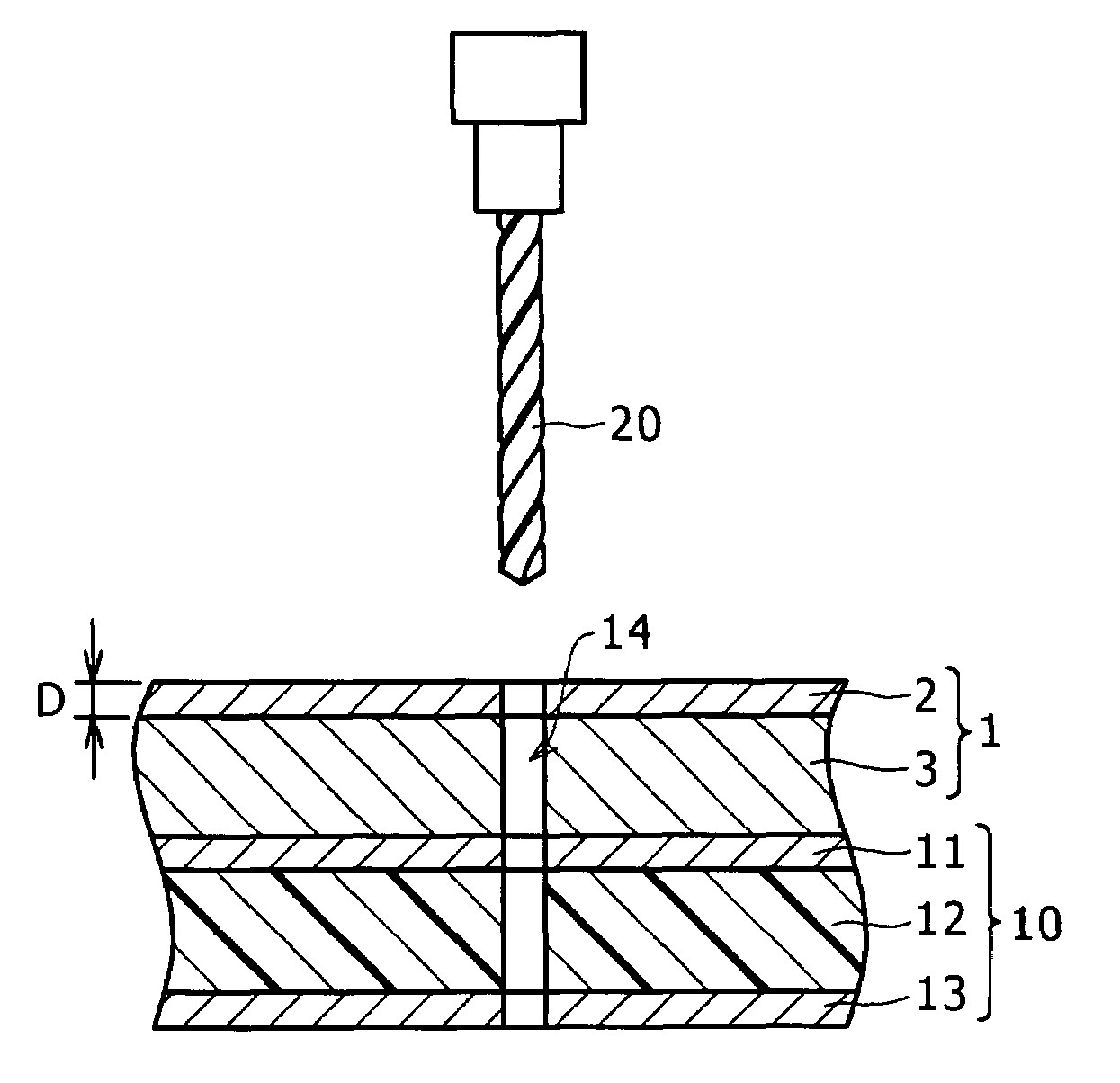
[0050]Each of resins of resin symbols A to G shown in Table 1 was fed into a uniaxial kneader / extruder and melted and kneaded therein to be in a uniform melting condition, then the resin in such a condition was extruded from a T-die mounted on a tip of the extruder, so that a film 100 μm in thickness was prepared. The film was laminated on a heated, pure aluminum plate specified by JIS) 100 μm in thickness while being fused to the aluminum plate, so that a resin-coated metal plate for drilling a printed wiring board was prepared.

[0051]Manufacturer names and trade names (grade) of used resins, lubricants, paraffin wax, and surfactants are as follows.

[0052]Ethylene-Ethylacrylate Copolymer Resin (1)

[0053]EVAFLEX (registered trademark)-EEA, Grade: A-701, manufactured by DU PONT-MITSUI POLYCHEMICALS CO., LTD.

[0054]Ethylene-Ethylacrylate Copolymer Resin (2)

[0055]EVAFLEX-EEA, Grade: A-704, manufactured by DU PONT-MITSUI POLYCHEMICALS CO., LTD.

[0056]Ethylene-Ethylacrylate Copolymer Resin (3...

examples 8 to 13

[0093]Using a resin of resin symbol A shown in Table 1, resin-coated metal plates for drilling the printed wiring board were prepared in the same way as in the example 1 except for setting film thickness to be 30, 40, 150, 200, 250 and 300 μm. Table 2 shows used film thickness and thickness of pure aluminum plates.


PUM

PropertyMeasurementUnit
melting peak temperatureaaaaaaaaaa
temperatureaaaaaaaaaa

Abstract

A resin-coated metal plate used as a protective plate in drilling a printed wiring board has a metal plate and a resin film including a thermoplastic resin coated on at least one surface of the metal plate. A melting peak temperature of the thermoplastic resin is in a range of 60-120° C., and in a TMA curve, a temperature difference exhibited by the thermoplastic resin is within a range of 5° C. to 30° C. in a period while penetration of the probe is changed from 10% to 100% of the resin thickness in a temperature range of 20° C. to 200° C.

Description

BACKGROUND OF THE INVENTION[0001]1. Field of the Invention[0002]The present invention relates to a resin-coated metal plate used as a protective back plate for efficiently obtaining high-quality products in drilling as one of steps of manufacturing a printed wiring board, and a method of drilling a printed wiring board using the resin-coated metal plate.[0003]2. Description of the Related Art[0004]The printed wiring board is for mounting electronic components and electrically connecting between the electronic components, and extremely important as an internal component of an electric product. In manufacturing the printed wiring board, as one of steps of manufacturing the board, there is a step of forming through-holes in a sectional direction in order to enable current supply between the uppermost layer and the lowermost layer of the printed wiring board. The through-holes are indispensable for the printed wiring board, and typically the number of the through-holes is large, therefo...

Claims


Application Information

Patent Timeline
Patent Type & Authority Patents(United States)
IPC IPC(8): B23B51/06B41L13/00
CPCB23B35/005H05K3/0047B23B2228/36H05K2201/0129H05K2203/0214Y10T29/49156Y10T29/49126Y10T29/5317Y10T29/49165Y10T29/5313Y10T29/49124B26F1/16H05K3/00
Inventor YOSHIKAWA, EIICHIROFUJISAWA, AKITOSHI
Owner KOBE STEEL LTD
Why Eureka
Try Eureka