Drive mechanism for a track mounted body

a technology of drive mechanism and track, which is applied in the direction of dismountable cabinets, locomotive transmissions, rope railways, etc., can solve the problems of adding cost and complexity to the shelving unit, and achieve the effects of avoiding slippage of the drive wheel, high friction, and high friction coefficien

Active Publication Date: 2009-09-15
GLIDESTORE FREETRACK PTY LTD
View PDF18 Cites 4 Cited by
  • Summary
  • Abstract
  • Description
  • Claims
  • Application Information

AI Technical Summary

Benefits of technology

[0012]The above invention avoids the need to have a drive axle mounted through the base of each shelf unit. In addition, it enables a simple arrangement to be attached to an existing shelf unit to convert it from a shelf unit that needs to be manually pushed along the tracks to a unit that incorporates a drive mechanism.
[0014]The drive wheel applies force to move the body by pushing against the surface or ground on which the body is mounted. Preferably, the periphery of the drive wheel comprises a high friction material such as a polyurethane material and surface against which the periphery of the wheel engages may also be roughened or have a high coefficient of friction to avoid slippage of the drive wheel.

Problems solved by technology

The need to mount a shaft within the base of the shelf unit results in added cost and complexity to the shelving unit.

Method used


Image

  • Drive mechanism for a track mounted body
  • Drive mechanism for a track mounted body
  • Drive mechanism for a track mounted body

Examples


Embodiment Construction

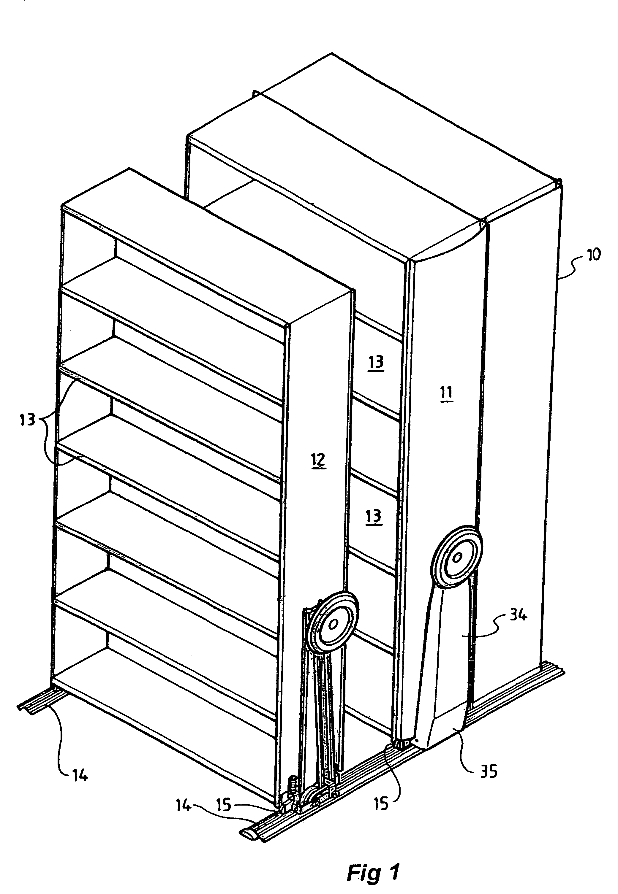
[0023]Referring to FIG. 1, there are three shelf units 10, 11 and 12 with shelves 13. Shelf units 11 and 12 are mounted to load bearing tracks 14 via wheels 15. Tracks 14 provide a longitudinal recess within which the wheels 15 locate. A pair of wheels 15 are used at each side of the shelf units 11 and 12 and are rotatably mounted about a horizontal axis within a housing which is attached at each side of the unit 11 and 12.

[0024]The shelf unit 10 is an end shelf unit and therefore is fixed with respect to the tracks 14. Shelf units 11 and 12 are moved along the tracks 14 to provide access between various pairs of shelves. For example, shelf unit 11 can be moved so as to open up access between shelf unit 11 and 10.

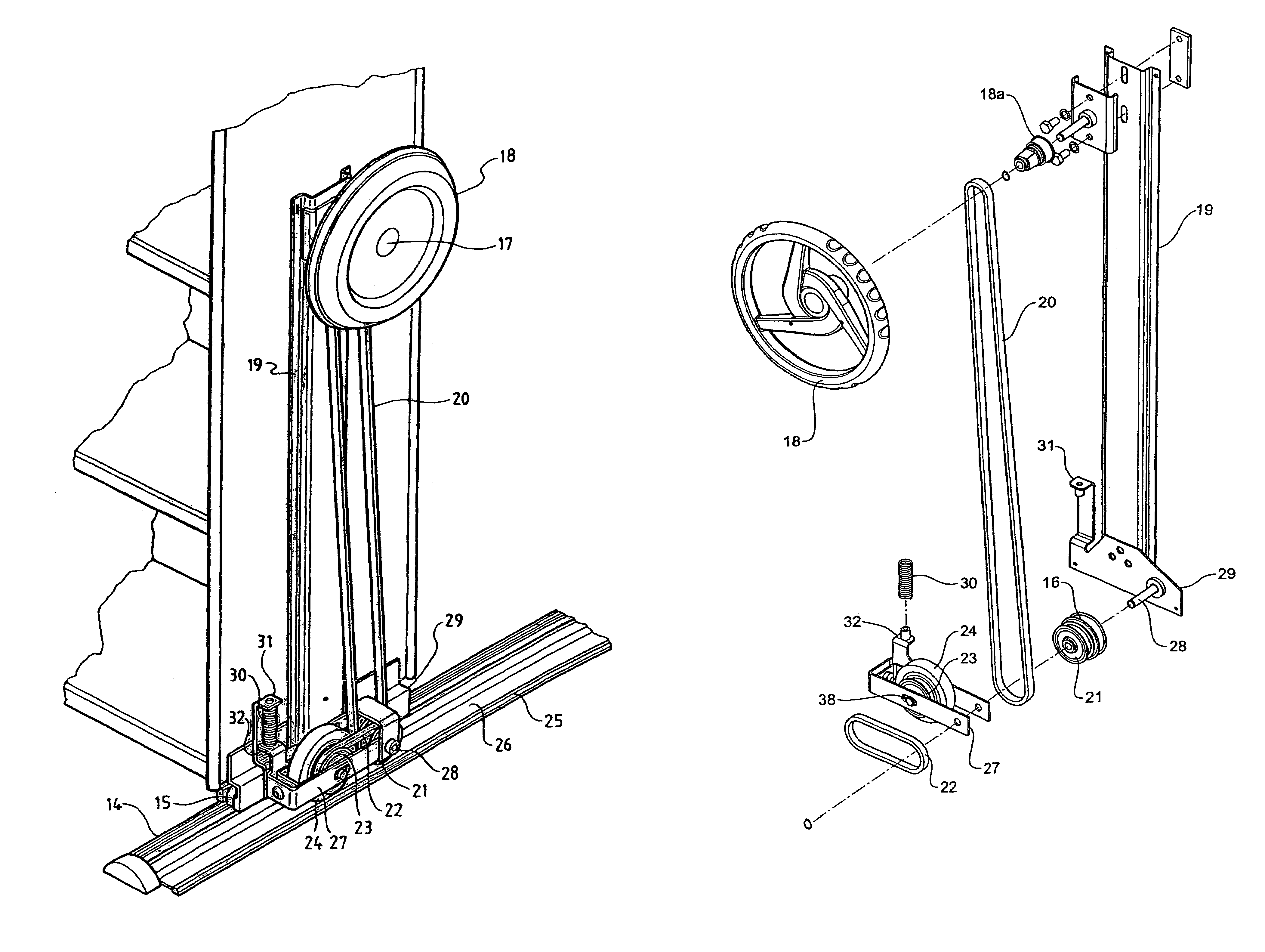
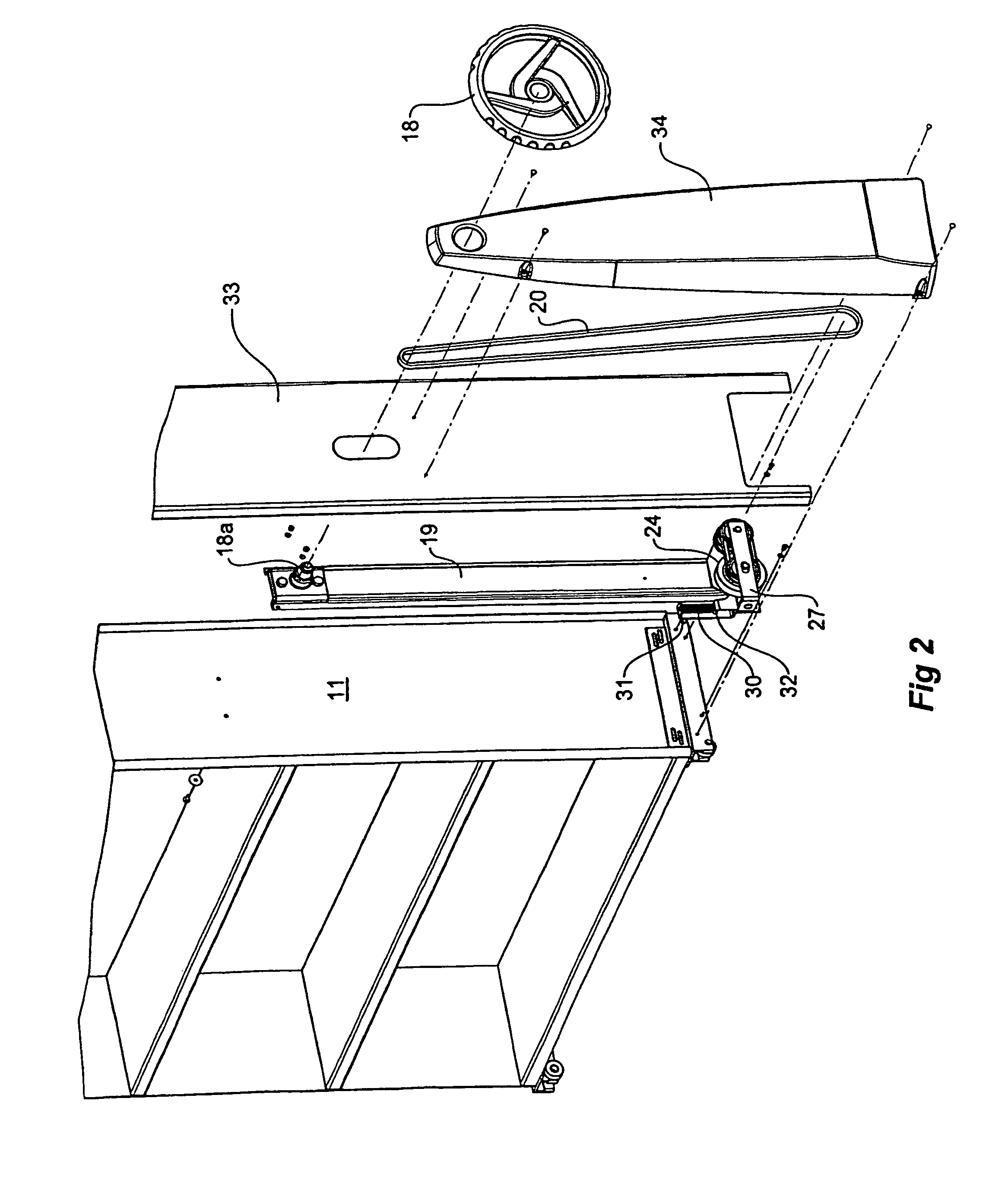
[0025]FIGS. 2, 3 and 4 show more detailed views of the drive mechanism. It has an actuator that comprises a drive shaft 17 to which a hand operated wheel 18 is attached. The drive shaft 17 is rotatably secured to a column 19 with column 19 attached to the side of the shelf ...


PUM


Abstract

A drive mechanism for a body where the body has a plurality of load bearing and track engaging wheels that allow the body to move back and forth along a track that comprises an actuator attached to the body that is manually or mechanically driven, a non-load beating drive wheel that is attached with respect to the body so that it engages a stationary surface adjacent the body and a drive coupling mechanism between the actuator and the drive wheel wherein actuation of the actuator causes rotation of the drive wheel which moves the body along the tracks. The invention provides a convenient mechanism of attaching a drive mechanism to a body and to enable easier movement of track mounted bodies.

Description

[0001]This invention relates to a drive mechanism for a track mounted body and in particular to a mechanism that enables movement of the body along the tracks without the use of a load bearing drive wheel.BACKGROUND OF THE INVENTION[0002]1. Field of the Invention[0003]An example of where the invention will find application are track mounted shelving or cabinet units. Such shelving units are designed to provide compact storage by having the shelving units abut against one another with only one access opening being provided within which the shelves can be accessed. The shelves can be separated by moving them along the track to open up access at different points along the assembled shelves.[0004]2. Description of the Related Art[0005]In many instances, shelves are moved manually although it is common to provide a manual crank mechanism or electric drive means to move the shelves. This is particularly necessary when each shelving unit carries a heavy load.[0006]The conventional means of...

Claims


Application Information

Patent Timeline
Patent Type & Authority Patents(United States)
IPC IPC(8): B61C9/00A47B53/02A47B96/00
CPCA47B53/02
Inventor PARKER, BRIAN MAURICECAMPBELL, GEORGE GILES
Owner GLIDESTORE FREETRACK PTY LTD
Why Eureka
Try Eureka