Electronically-controlled throttle body

a throttle body and electronic control technology, applied in the direction of electric control, combustion engines, charge feed systems, etc., can solve the problems of increasing the reduction gear ratio, the increase of the necessary motor driving torque, and the device cannot be easily downsized, so as to reduce the driving torque required for the motor, reduce the diameter of the motor shaft, and reduce the effect of the motor downsizing

Inactive Publication Date: 2009-09-15
MITSUBISHI ELECTRIC CORP
View PDF6 Cites 9 Cited by
  • Summary
  • Abstract
  • Description
  • Claims
  • Application Information

AI Technical Summary

Benefits of technology

[0010]The present invention has been made to resolve problems as described above, and aims at providing an electronically-controlled throttle body in which the inter-shaft distance between the motor shaft and the valve shaft is shortened so as to downsize the device as a whole and driving torque required for the motor is reduced so as to reduce the diameter of the motor shaft, resultantly enabling downsizing of the motor.
[0011]In addition, by making two the number of parallel gear shafts, the invention aims at reducing locations where high accuracy of inter-shaft distances is needed, so as to resolve problems in manufacturing the body when it is resinified.
[0014]According to the present invention, an electronically-controlled throttle body can be obtained in which the inter-shaft distance between the motor shaft and the valve shaft is shortened so that the device can be downsized as a whole, as well as the diameter of the motor shaft is made smaller so that the motor can be downsized.
[0015]Moreover, by making two the number of parallel gear shafts, the number of locations where high accuracy of inter-shaft distances is required becomes less, so that an electronically-controlled throttle body can be obtained in which manufacturing problems can be resolved when the body is resinified.

Problems solved by technology

However, in a conventional electronically-controlled throttle body as described above, since torque is transmitted by the spur gear two-stage reduction gear mechanism, inter-shaft distances each are needed between the output gear shaft and the intermediate gear shaft and between the intermediate gear shaft and the input gear shaft, depending on each gear's pitch radius; therefore, the size of device is determined by those inter-shaft distances, causing a problem in that the device can not be easily downsized.
Moreover, trying to downsize the device needs to limit the pitch radius of each gear, which needs to limit the number of teeth of each gear accordingly; thereby, it becomes difficult to increase reduction gear ratios, resulting in necessary motor driving torque being greater, which has been an inhibiting factor of downsizing the motor.
Moreover, when a spur-gear two-stage reduction gear mechanism is used for the reduction gear mechanism, the output gear fixed on the motor shaft undergoes reaction force from the intermediate gear; the reaction force generates to the motor shaft bending moment whose fulcrum lies on a bearing of the motor shaft; consequently, the motor shaft undergoes both bending moment and driving torque, so that the strength of motor shaft can not be easily decreased.
Therefore, the diameter of the motor shaft can not be reduced in order to secure the strength of the motor shaft, which resultantly has been an inhibiting factor of downsizing the motor.
Therefore, there has been a problem in that, even if the body is tried to be made of resin, for example, intending to cost down, production of the body becomes extremely difficult due to difficulties in ensuring accuracy of inter-shaft distances among those three gear shafts.
However, when the motor is located higher than a throttle valve shaft in a conventional electronically-controlled throttle body, there is concern about interference with the hood, and in order to avoid the interference, there has been such a problem as the hood line needs to be elevated.
Meanwhile, when the motor is located lower than the throttle valve shaft, a hot water heating passage can not be provided on the ground side of the inner wall of the air-intake passage where condensed water is likely to deposit, which has made it difficult to take efficient countermeasures against freezing.

Method used


Image

  • Electronically-controlled throttle body
  • Electronically-controlled throttle body
  • Electronically-controlled throttle body

Examples


embodiment 1

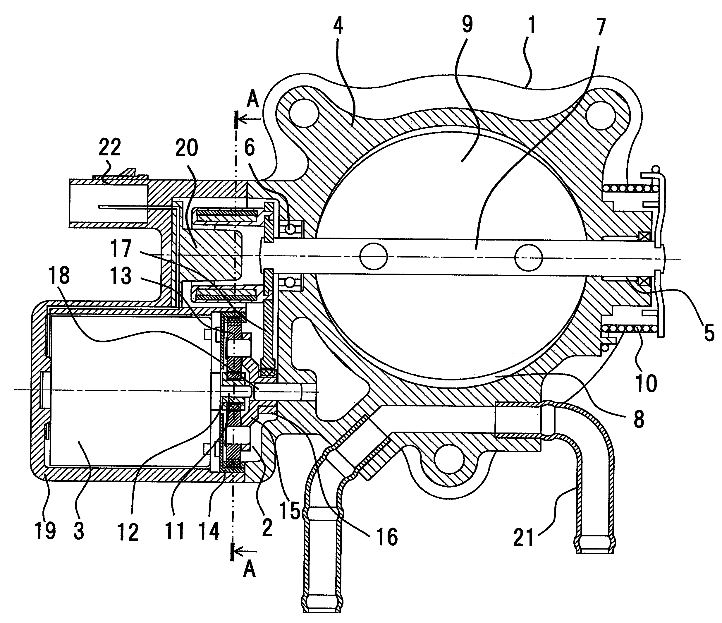
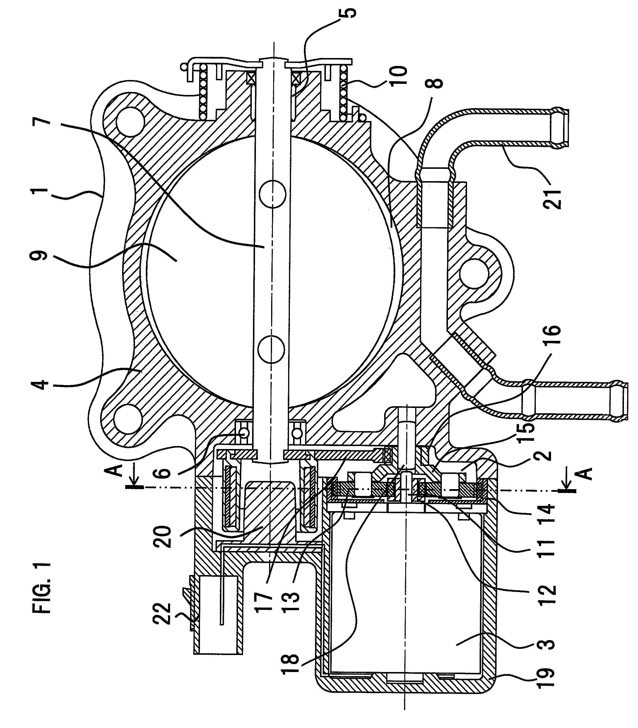
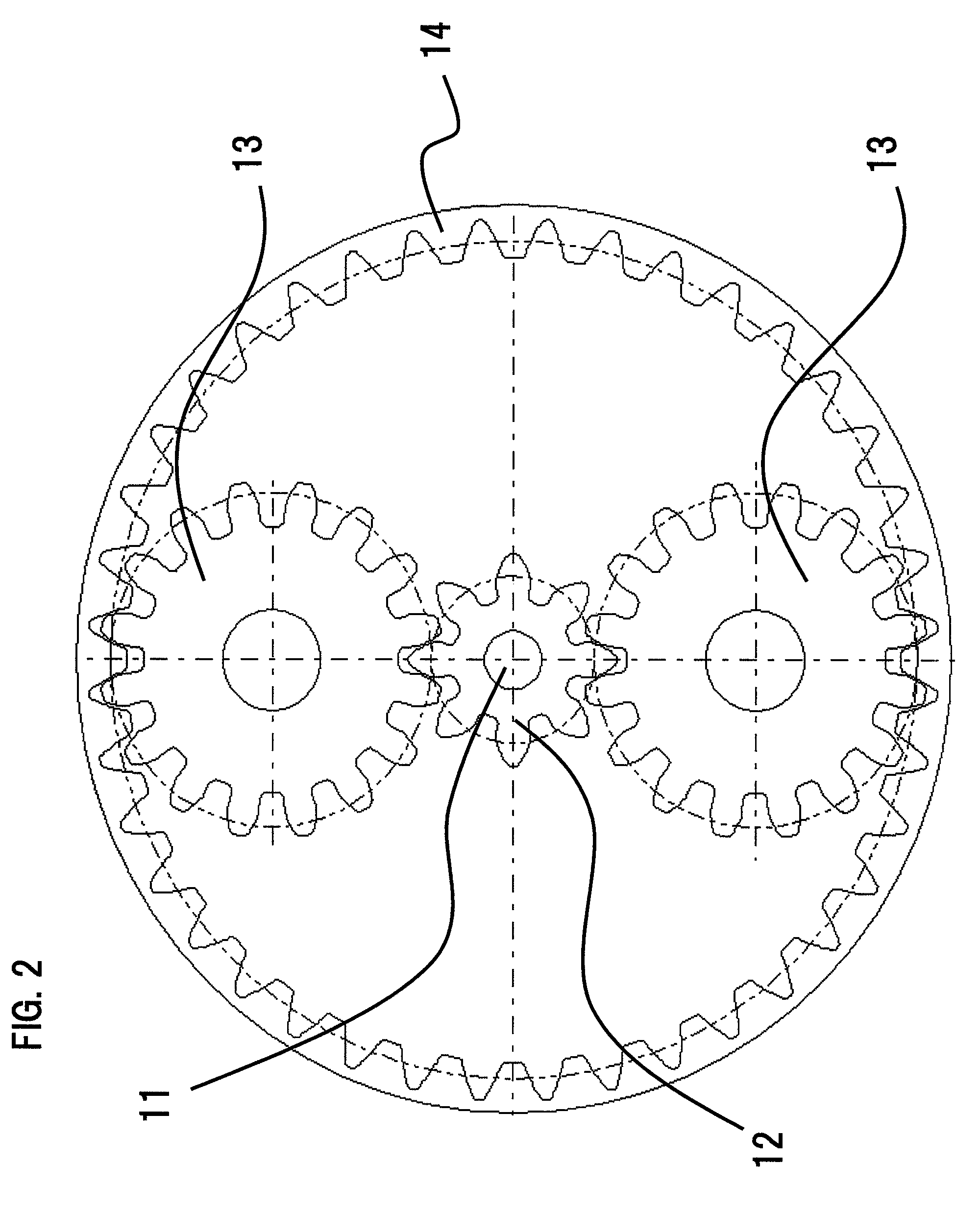
[0021]Hereinafter, Embodiment 1 of the present invention will be explained referring to FIG. 1 and FIG. 2. Here, parts that have the same reference numerals in each figure represent the same or corresponding ones. FIG. 1 is a cross-sectional view showing an electronically-controlled throttle body according to Embodiment 1 of the present invention; FIG. 2 is a partial cross-sectional view along the A-A line in FIG. 1. In FIG. 1 and FIG. 2, the electronically-controlled throttle body includes a throttle valve 1, a reduction gear mechanism 2 connected to the throttle valve 1 and a motor connected to this reduction gear mechanism 2.

[0022]The throttle valve 1 includes a body 4, a valve shaft that is rotatably supported by the right and left walls of the body 4 via a first bearing 5 and a second bearing 6, a valve disc 9 that is fixed on the valve shaft 7 and varies an opening area of an air-intake passage 8 formed in the body 4, and a spring 10 that is provided in the proximity of the fi...

embodiment 2

[0035]FIG. 3 is a cross-sectional view showing an electronically-controlled throttle body according to Embodiment 2 of the present invention. In the figures, parts that have the same reference numerals in FIG. 1 and FIG. 2 represent the same or corresponding ones, eliminating duplicate explanations.

[0036]In the electronically-controlled throttle body according to Embodiment 2, the body 4 is molded out of resin (PPS) and the holder 23 made of brass is insert-molded into the body 4. The bearing 6 that supports the valve shaft 7 and the pin 18 that supports the smaller gear 16 are press-inserted into the holder 23.

[0037]According to Embodiment 2, since the number of gear shafts is less by one than that of a conventional electronically-controlled throttle body provided with a spur-gear two-stage reduction gear mechanism, and the number of locations where high inter-shaft accuracy is needed is also less, necessary dimensional accuracy can be assured even if the body 4 is molded out of re...


PUM


Abstract

An electronically-controlled throttle body includes a throttle valve having a valve disc, fixed on a valve shaft rotatably supported in a body inside which an air-intake passage is formed, for varying an opening area of the air-intake passage; a reduction gear mechanism connected to the valve shaft of the throttle valve; and a motor connected to the reduction gear mechanism; rotational drive power from the motor is transmitted to the valve shaft via the reduction gear mechanism, and the opening area of the air-intake passage is varied by rotatably moving the valve disc. The reduction gear mechanism includes a planetary gear mechanism and a spur gear reduction gear mechanism, rotational drive power from the motor is decelerated by the planetary mechanism, and the decelerated rotational drive power is further decelerated by the spur gear reduction gear mechanism, and then transmitted to the valve shaft.

Description

BACKGROUND OF THE INVENTION[0001]1. Field of the Invention[0002]The present invention relates to an electronically-controlled throttle body in which a valve disc is rotatably moved, via a reduction gear mechanism, by a motor driven in response to gas pedal operations.[0003]2. Description of the Related Art[0004]As shown in Japanese Laid-Open Patent Publication No. 2002-266666 (hereinafter referred to as Patent Document 1), an electronically-controlled throttle body has been heretofore known in which an opening degree of a valve disc is controlled, via a reduction gear mechanism, by a motor driven in response to gas pedal operations. In the throttle body shown in this Patent Document 1, in order to increase torque generated by the motor up to the torque needed for controlling an opening degree of the valve disc, a spur gear two-stage reduction gear mechanism is employed that performs two-step speed reduction by transmitting torque generated by the motor from an output gear fixed on t...

Claims


Application Information

Patent Timeline
Patent Type & Authority Patents(United States)
IPC IPC(8): F02D11/04F02D11/10
CPCF02D9/105F02D9/1065F02D41/0002F02D9/1035F02M31/10F02M31/102F02D9/107F02D9/108F02D2200/0404Y02T10/42F02D2011/102Y02T10/12Y02T10/40
Inventor TSUGAMI, HIROMICHINAGAHORI, TATSUROMORIGUCHI, TERUHIKOISOZUMI, SHUZO
Owner MITSUBISHI ELECTRIC CORP
Why Eureka
Try Eureka