Pedicle screw with vertical adjustment

a technology of pedicle screws and vertical adjustment, which is applied in the field of spinal fixation devices, can solve the problems of difficult and often impossible to line up pedicle screws in one plane, and places significant challenges on the mechanical design of the linking system

Inactive Publication Date: 2009-09-15
INT SPINAL INNOVATIONS
View PDF32 Cites 117 Cited by
  • Summary
  • Abstract
  • Description
  • Claims
  • Application Information

AI Technical Summary

Benefits of technology

[0009]2. Clamping mechanism allows substantial vertical travel along the screw trajectory contributing to additional degrees of freedom. This adds substantial flexibility particularly when more then 3 screws need to be connected.
[0010]3. Connector can be snapped onto the screw head after screw is placed into the bone. This keeps hardware profile minimal and improves exposure for delivery of graft material. It also allows for all the connectors and rods to be assembled outside of the wound. This is particularly valuable in small direct exposures characteristic of the minimally invasive approach.

Problems solved by technology

Anatomy of individual patient makes it difficult and often impossible to line up pedicle screws in one plane.
This places significant challenges on the mechanical design of the linking system.

Method used


Image

  • Pedicle screw with vertical adjustment
  • Pedicle screw with vertical adjustment
  • Pedicle screw with vertical adjustment

Examples


Embodiment Construction

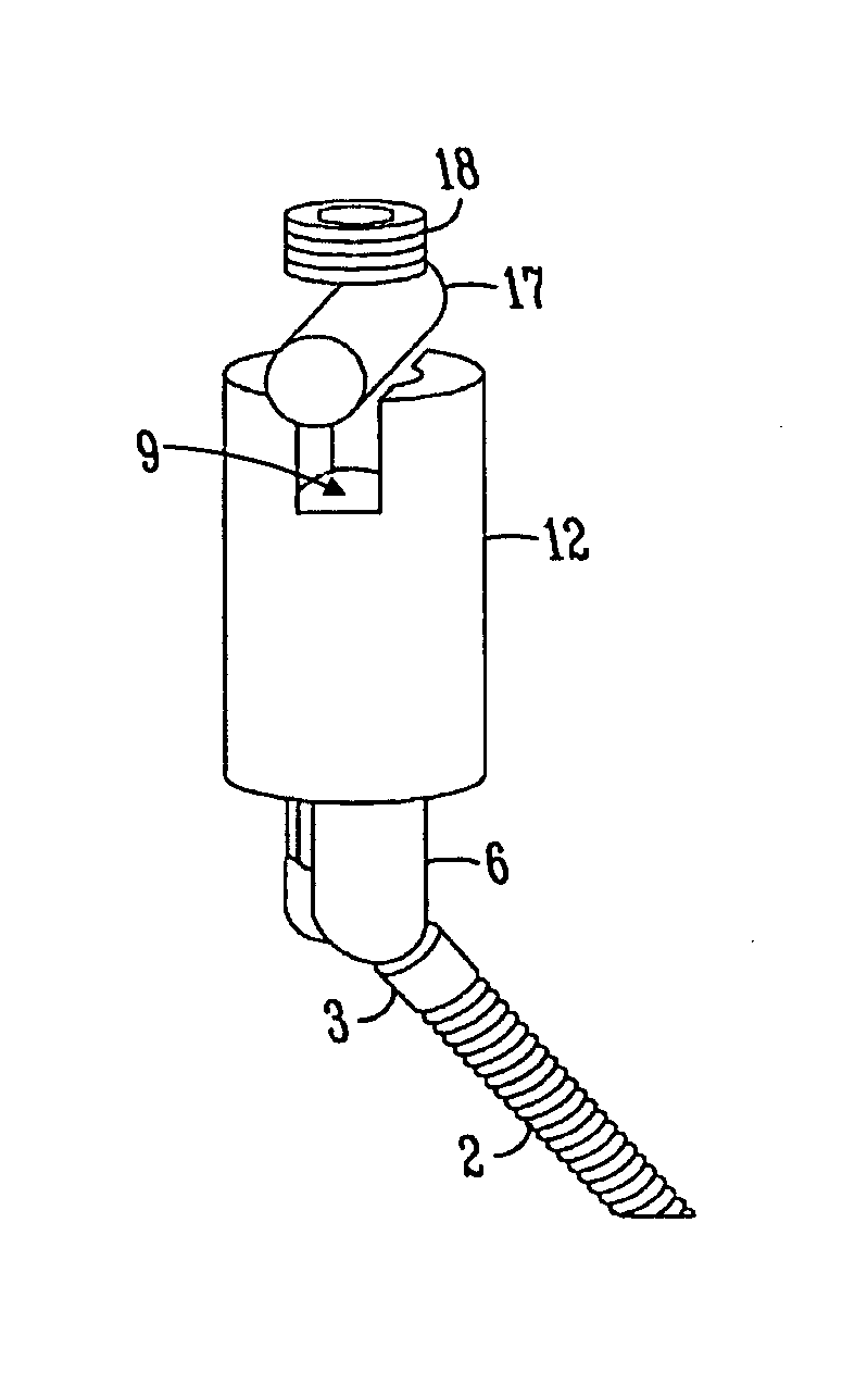
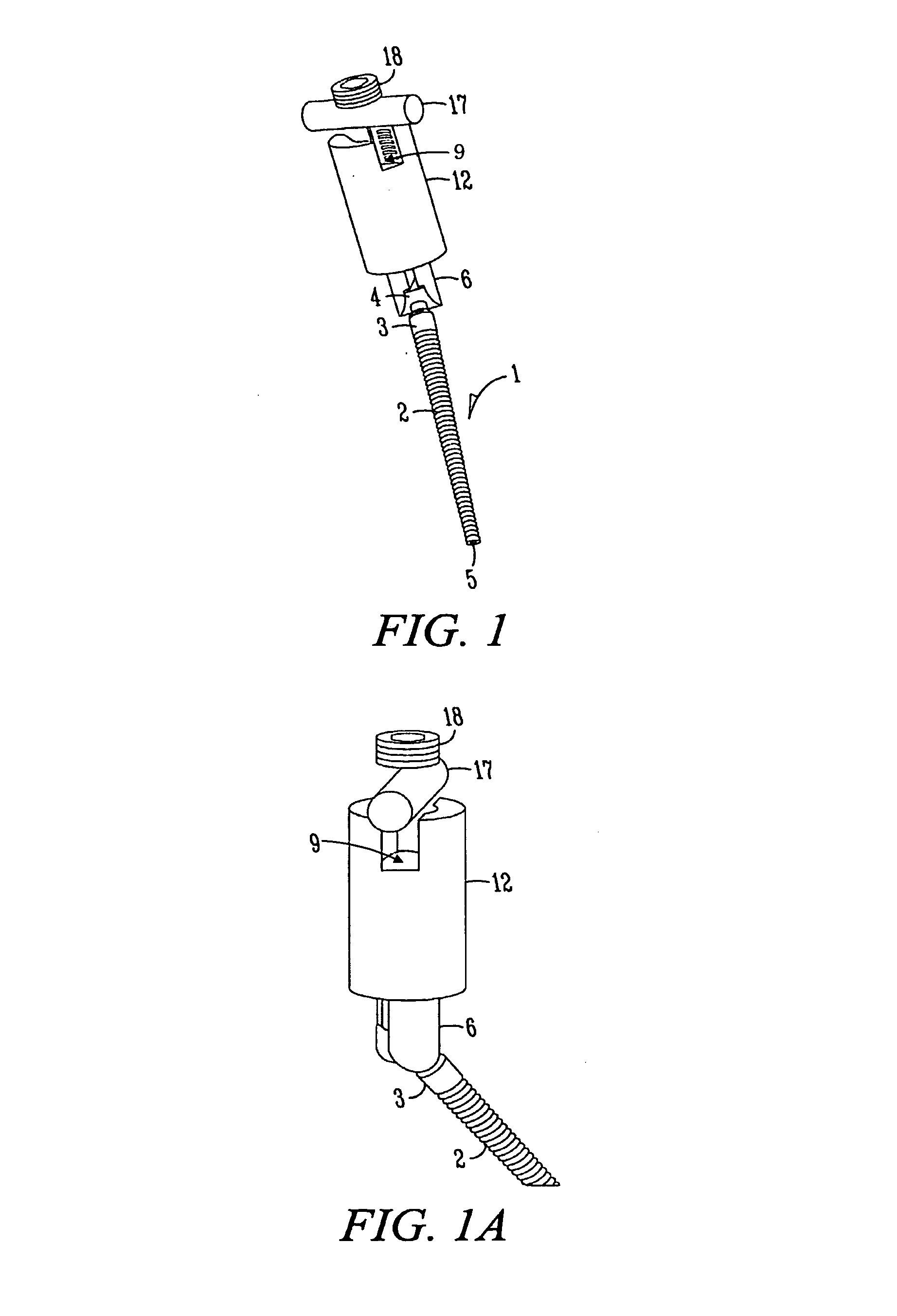
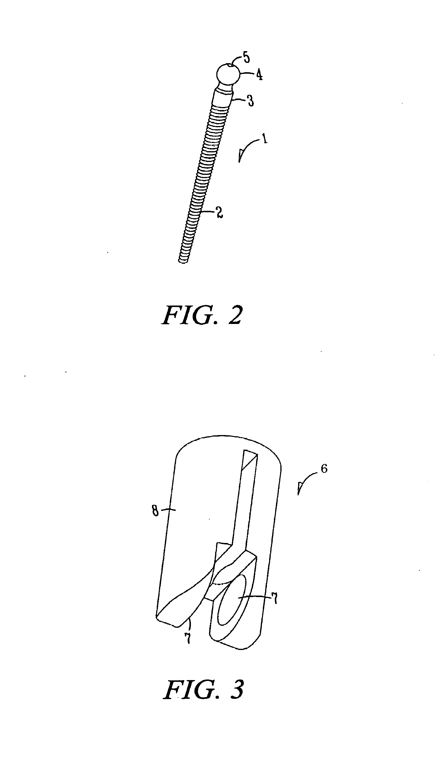
[0013]In its preferred embodiment device consists of a screw, screw clamp, rod receiver, compression spacer, rod and nut (FIG. 1).

[0014]Screw has a long threaded portion placed into the bone and a protruding cylindrical shaft with a spherical head (FIG. 2). A compressible cylindrically shaped screw clamp of substantial thickness (FIG. 3) has a spherical cut-out at one end such that it fits precisely over the screw head (FIG. 4). It pivots about the screw head with angle of deflection greater then ninety degrees and 360 degrees of revolution through the entire range of deflection.

[0015]Screw clamp (FIG. 6) tightly fits into cylindrical assembly consisting of the rod receiver and compression spacer (FIG. 7). Rod receiver has a travel tube with a tapered end which fits over the screw clamp. The other end forms the seat for the rod bounded by threaded walls (FIG. 8). Up and down movement of the screw clamp within the rod receiver allows for a vertical adjustment. Compression clamp is a ...


PUM


Abstract

An apparatus for rigid fixation of individual vertebra to the stabilizing rod. It consists of an anchor secured to the vertebra and a connector with multiple degrees of freedom linking each anchor to a rod. Pressure from the rod against a connector engages internal constricting mechanism and eliminates movement within the connection. This results in rigid fixation between individual anchors and the rod.

Description

FIELD OF INVENTION[0001]This invention relates to a spinal fixation device. More specifically, the present invention relates to an implant bridging together two or more vertebra by anchoring to the posterior vertebral arch and pedicles.BACKGROUND[0002]Spinal fusion is utilized to correct painful movement across degenerated or unstable spinal segment and is supplemented by fixation with screws. Screws are commonly placed through the posterior vertebral arch. Multiple fixation targets have been used in the past including facets, spinal processes, lamina, transverse processes, lateral masses and pedicles. Currently fixation through the pedicles offers the most robust purchase and is utilized when possible.[0003]Screws are implanted from the back to the front of the vertebra with one screw inserted per each side per vertebra. Individual screws have to be rigidly linked to eliminate movement between corresponding vertebras. (U.S. Pat. No. 5,474,555 Puno et al.). Anatomy of individual pat...

Claims


Application Information

Patent Timeline
Patent Type & Authority Patents(United States)
IPC IPC(8): A61B17/70
CPCA61B17/7038A61B17/7037A61B17/7032A61B17/863
Inventor AFERZON, JOSEPH
Owner INT SPINAL INNOVATIONS
Why Eureka
Try Eureka