Atomic force microscope

a microscope and atomic force technology, applied in the direction of mechanical measurement arrangements, mechanical roughness/irregularity measurements, instruments, etc., can solve the problems of reducing measurement accuracy, causing a pattern deviation between a probe and the focus of an optical system, and unable to effect high-accuracy measurement. achieve the effect of high accuracy

Inactive Publication Date: 2009-09-22
CANON KK
View PDF14 Cites 10 Cited by
  • Summary
  • Abstract
  • Description
  • Claims
  • Application Information

AI Technical Summary

Benefits of technology

[0029]A principal object of the present invention is to provide an atomic force microscope capable of measuring a shape at high accuracy by causing a focus position of an optical system to follow a position of a probe.

Problems solved by technology

(1) Patent deviation between a probe and focus of an optical system is caused to occur during scanning.
For this reason, it is impossible to effect high-accuracy measurement unless the focus of “optical lever” is accurately formed on the probe.
As a result, a focus position of the optical system is deviated from a reflection surface of the probe, so that measurement accuracy is reduced.
However, in the case of an uneven shape having an unevenness of several tens of microns or above, reflected light is diffused.
As a result, it is difficult to effect measurement at high accuracy.
More specifically, during the operation of the scanner, the light-passing portion of each of the lenses constituting the optical system is changed, so that position deviation of focus of the optical system is caused to occur.
(2) It is difficult to detect a focus position.
However, in U.S. Pat. No. 5,560,244 and JP-A Hei 5-312561, these positions cannot be measured.
However, this is very complicated, thus being less practical.
(3) It is difficult to adjust a focus position with lapse of time.
However, an apparatus such as the scanner causes a change with lapse of time due to deterioration of parts etc., so that an amount of the change is not negligible.
In U.S. Pat. No. 5,560,244 and JP-A Hei 5-312561, the light source and the probe are fixed to the scanner having the optical system, so that it is not easy to effect the adjustment.
However, this adjustment is very complicated, so that complicated adjustment performed frequently is a large problem from a practical viewpoint.
(4) Alignment adjustment during replacement of a probe is complicated.
An end of the probe is deteriorated due to wearing or the like, so that the probe is a consumable part.
When the probe is replaced, a position of the probe is always deviated due to a production error or a mounting error.
However, in U.S. Pat. No. 5,560,244 and JP-A Hei 5-312561, it is difficult to detect the focus position and adjustment of the focus position is complicated, so that alignment adjustment during replacement of the probe is also complicated.
From a practical viewpoint, complicated adjustment performed frequently is large deficiency.
(5) It is difficult to meet a multi-probe.
In a conventional technique, it is difficult to develop multi-probing capable of simultaneously measure many points using a large number of probes close to each other with a spacing of, e.g., about 100 μm.
However, it is impossible to dispose all these constitutional elements (members) close to each other.
Particularly, the lenses require some aperture ratio for focusing light, so that it is difficult to reduce the size of the lenses.
Further, also in U.S. Pat. No. 5,560,244, a number of light sources and light detection means are similarly disposed close to each other, the light sources are provided to the end of the scanning, so that it is further difficult to reduce the size of the end of the scanning.
(6) It is difficult to effect high-accuracy measurement since the end of the scanner cannot be reduced in size.
In the conventional atomic force microscope including a heat generation source disposed in the neighborhood of a point of measurement, the high-accuracy measurement cannot be expected.
Further, it is necessary to attach the light source and an optical element for focusing light emitted from the light source onto the probe at the end of the scanner, so that a weight of the end of the scanner cannot be decreased.
When the end of the scanner is heavy, an error during scanning is also large.
Thus, the high-accuracy measurement cannot be also expected.

Method used


Image

  • Atomic force microscope
  • Atomic force microscope
  • Atomic force microscope

Examples


embodiment 1

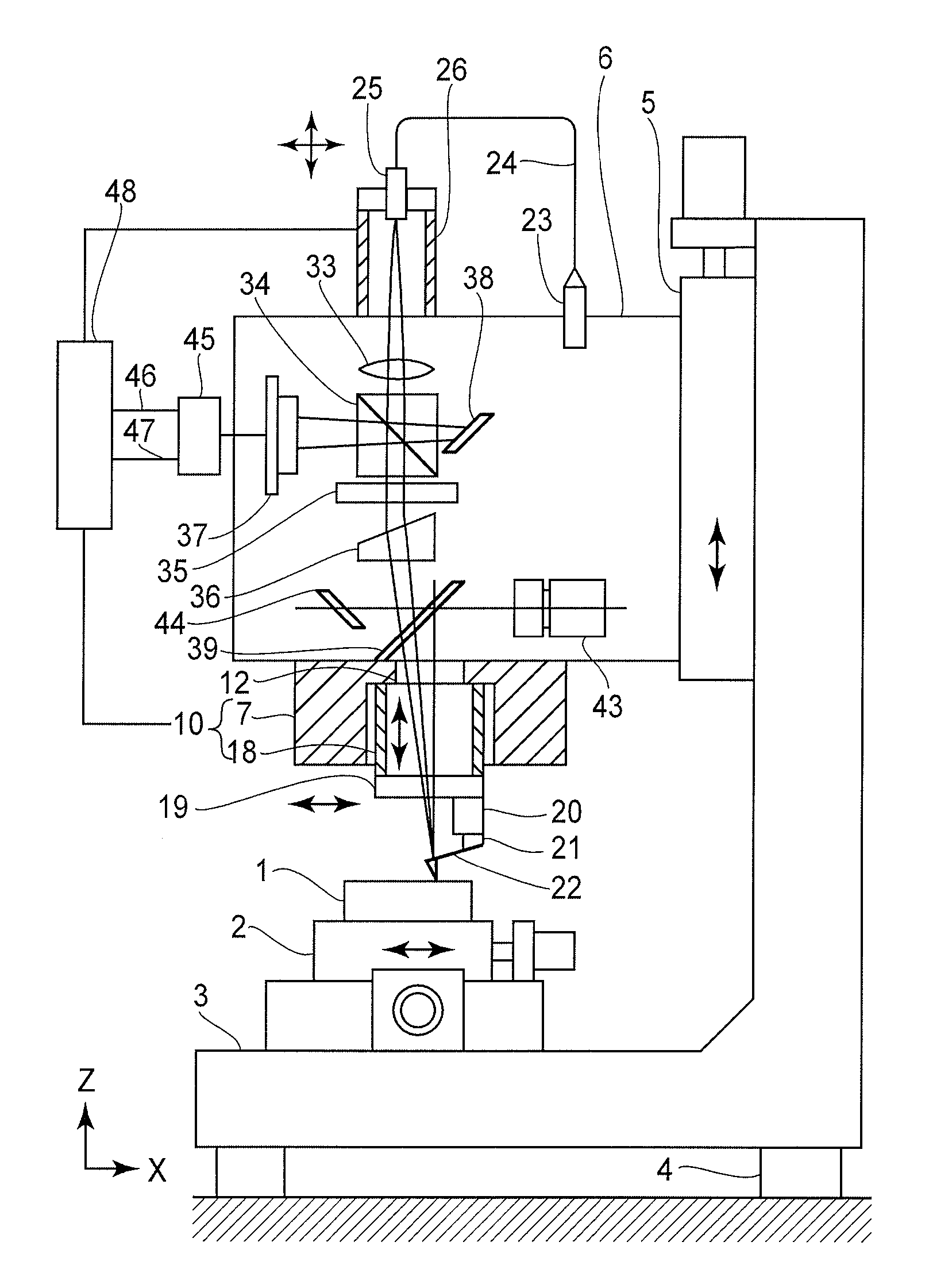
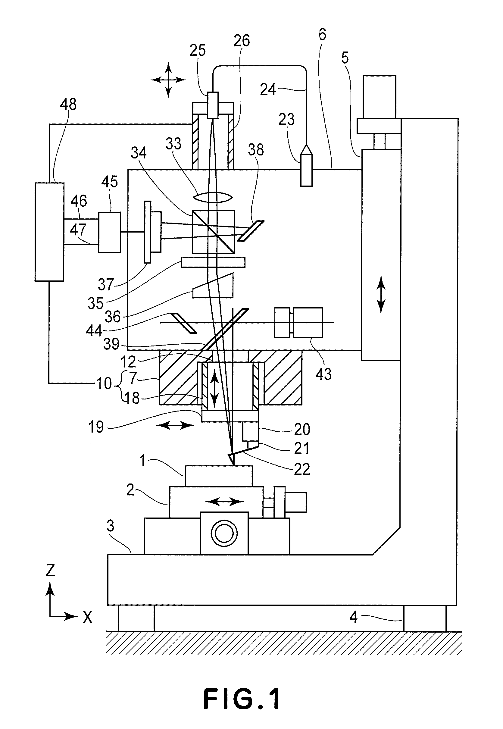
[0079]FIG. 1 shows an atomic force microscope according to Embodiment 1. A base 3 is disposed on a vibration isolation stand 4 and on the base 3, an XY coarse movement stage 2 is disposed. On the XY coarse movement stage 2, a member 1 to be measured is set. To a Z coarse movement stage 5 provided vertically to the base 3, a housing 6 is provided. The housing 6 holds an XY scanner 7 movable in X and Y directions.

[0080]FIG. 3 is a schematic view of the XY scanner 7 as seen from above (Z direction). A main assembly of the XY scanner 7 has a hinge mechanism cut from a metal material and is provided with four X plate spring portions 8 formed by wire cut processing, so that an X movement portion 9 is movably guided in X direction. In the X movement portion 9, an XY movement portion 10a is provided and guided by four Y plate spring portions 11. By this constitution, the XY movement portion 10a is movably guided in X and Y directions. At a center of the XY movement portion 10a, a through ho...

embodiment 2

[0162]FIG. 11 illustrates an atomic force microscope according to Embodiment 2. The atomic force microscope of this embodiment has the same constitution as that of the atomic force microscope of Embodiment 1 except that an auto focus apparatus is incorporated in an optical path of reflected light from the probe 22.

[0163]The auto focus apparatus is fixed to the housing and includes a half mirror 58, a lens 59, a cylindrical lens 61, and a four-piece photodiode 62.

[0164]Light reflected by the probe 22 is diffusive light since focus thereof is placed on the probe 22. The light is reflected by the beam splitter 34 and enters the half mirror 58. The transmitted light enters the light detection means 37 and the reflected light is converted into light converged by the lens 59 and passes through the cylindrical lens 61 to enter the four-piece photodiode 62.

[0165]The auto focus apparatus utilizing astigmatism described above introduces therein light branched by the half mirror disposed in th...

embodiment 3

[0173]FIG. 14 illustrates an atomic force microscope according to Embodiment 3. The atomic force microscope of this embodiment has the same constitution as that of the atomic force microscope according to Embodiment 1 except that galvano-mirrors 71 and 72 are incorporated therein in an optical path of reflected light from the probe 22.

[0174]The galvano-mirror has been widely used as a light polarizing device capable of controlling an angle of a mirror at high speed by utilizing electromagnetic force etc. It is also possible to control the direction of light in two directions by combining two galvano-mirrors each capable of controlling one angle of rotation. Further, by disposing a planar galvano-mirror using a torsion bar in the optical system, the focus position can be moved at high speed.

[0175]In this embodiment, a light source 23 such as a semiconductor laser is provided fixedly to the housing 6 so that emitted light is guided into the optical fiber 24. The emission end 25 of the...


PUM

PropertyMeasurementUnit
depthaaaaaaaaaa
sizeaaaaaaaaaa
thresholdaaaaaaaaaa

Abstract

A surface shape of a member to be measured is measured by reflecting measuring light at a reflection surface of a probe and utilizing an atomic force exerting between the probe and utilizing an atomic force exerting between the probe and the member to be measured. In addition to a first scanner for driving the probe, a second scanner for moving a focus position of an optical system is provided. Position conversion data representing a correlation between amounts of control of the first scanner and the second scanner are obtained in advance. By synchronously driving the first scanner and the second scanner, the focus position of the optical system is caused to follow the probe to improve measurement accuracy.

Description

FIELD OF THE INVENTION AND RELATED ART[0001]The present invention relates to an atomic force microscope capable of measuring a minute shape on the order of subnanometers by using an optical lever for detecting displacement of a probe.[0002]A probe used in an atomic force microscope includes a flat spring portion having an end provided with a sharp pointed portion. On the flat spring portion, a reflection surface is formed. The probe is also called “cantilever” but is herein inclusively described as “probe”.[0003]FIG. 26 shows a constitution of a conventional atomic force microscope described in U.S. Pat. No. 5,560,244. The atomic force microscope effects measurement of a member 113 to be measured. A probe 114 is attached to a mount 120, and the mount 120 is attached to a lower end of a tube scanner 112 movable in X, Y and Z directions. A beam from a light source 110 is once focused by a lens 160 to form a point source 162 of light and is then focused onto a back surface of the probe...

Claims


Application Information

Patent Timeline
Patent Type & Authority Patents(United States)
IPC IPC(8): G01B5/28G01N13/16G12B21/22G01Q60/24G01B21/30G01Q70/06
CPCB82Y35/00G01B21/30G01Q70/06G01Q20/02G01Q60/38G01Q10/06
Inventor NEGISHI, MAHITO
Owner CANON KK
Why Eureka
Try Eureka