

Micromechanical motion sensor
a motion sensor and micro-mechanical technology, applied in the direction of instruments, turn-sensitive devices, calibration apparatus, etc., can solve the problems of undesirable effect and considerable impairment of the yaw rate sensor performan
- Summary
- Abstract
- Description
- Claims
- Application Information
AI Technical Summary
Benefits of technology
Problems solved by technology
Method used
Image

Examples
Embodiment Construction
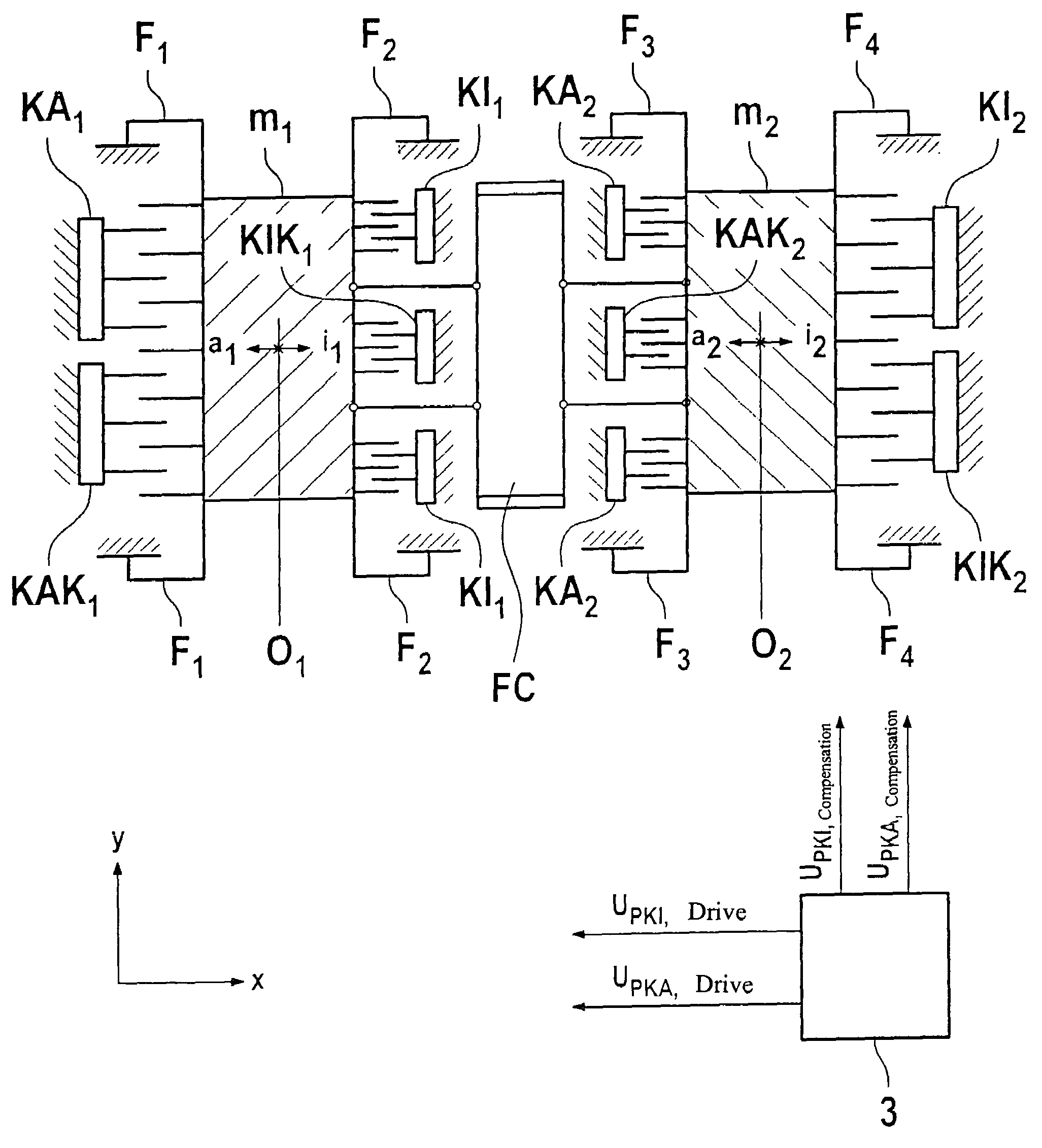
[0032]To compensate for the mechanical non-linearity of the bending bar, in addition to the previous drive signal (see FIG. 4), a compensation voltage is applied to the comb drive, which accurately compensates for the non-linear term of differential equation 2. It must be kept in mind that comb drives are able to apply forces in one direction only due to their operating principle. Thus, in the case of a positive deflection i, comb drive KA is responsible for the compensation, and in the case of negative deflection a, it is comb drive KI.
[0033]The compensation voltage curve results from the analytical relationships for the yaw rate sensor. The moment to be compensated results from equation 2.
Mcomp=ktZ,0ktzNLγ3 (4)
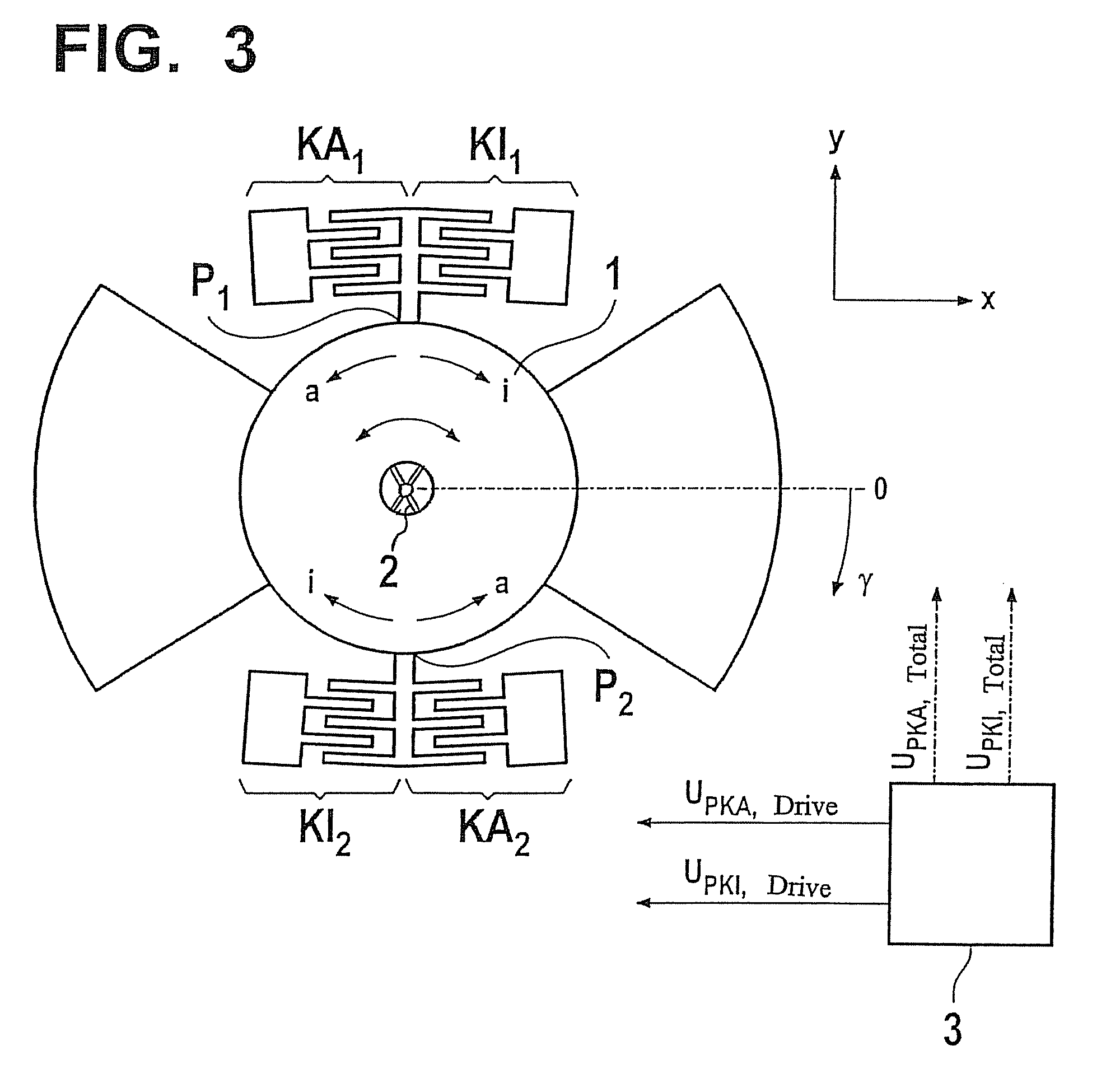
[0034]If this moment is to be applied via the available comb drives (KI1, KI2 and KA1, KA2), the following equation results:
[0035]Mcomp=2(UPKI,PKA-UPCM)2ɛ0hd0kstrayncombreff=ktz,0ktz,NL·γ3(5)
where Kstray is a correction factor for taking into account stray field effe...
PUM
 Abstract
Description
Claims
Application Information