Clutch release mechanism

a technology of release mechanism and ball, which is applied in the direction of mechanical actuated clutches, friction clutches, and clutches, can solve the problems of low assemblyability and achieve the effect of reducing vibration of balls and improving assemblyability

Active Publication Date: 2009-09-22
HONDA MOTOR CO LTD
View PDF6 Cites 2 Cited by
  • Summary
  • Abstract
  • Description
  • Claims
  • Application Information

AI Technical Summary

Benefits of technology

[0007]In view of such a problem, it is an object of the invention to provide a clutch release mechanism which can restrain vibrations of the ball while allowing the ball to be loosely fitted when it is not in operation to ensure the engaged state of the clutch. Thus, the assembleability is improved.
[0011]According to an embodiment of the present invention, since the urging member for urging the ball unit in the direction of being slid toward the clutch cam plate is attached to the peripheral portion of the boss member, when the clutch release mechanism is not in operation, the ball unit comes apart from the receiving plate. Thus, the balls are brought into a loosely fitted state, while the balls are brought into abutment with the cam-like recesses of the clutch cam plate by the urging member. Therefore, vibrations of the balls can be restrained while allowing the balls to be loosely fitted when the clutch release mechanism is not in operation to ensure the engaged state of the clutch device. In addition, since the retaining member for restricting the ball unit from coming out from the boss member is mounted to the peripheral portion of the boss member, the possibility that the ball unit or the urging member comes out from the boss member when assembling the clutch release mechanism can be eliminated. Thus, the assembleability of the clutch release mechanism can be improved.
[0012]In addition, since the gap is defined between the outer peripheral surface of the outer race of the bearing and the inner surface of the collar member, eccentricity generated between the clutch release mechanism and the clutch device can be absorbed with a simple configuration.

Problems solved by technology

However, in the structure in the related art as described above, when the ball is loosely fitted between the fixed cam plate and the movable cam plate, there is a possibility that the ball is vibrated when an engine is in operation which results in a noise being made.
Thus, assembleability is low.

Method used


Image

  • Clutch release mechanism
  • Clutch release mechanism
  • Clutch release mechanism

Examples


Embodiment Construction

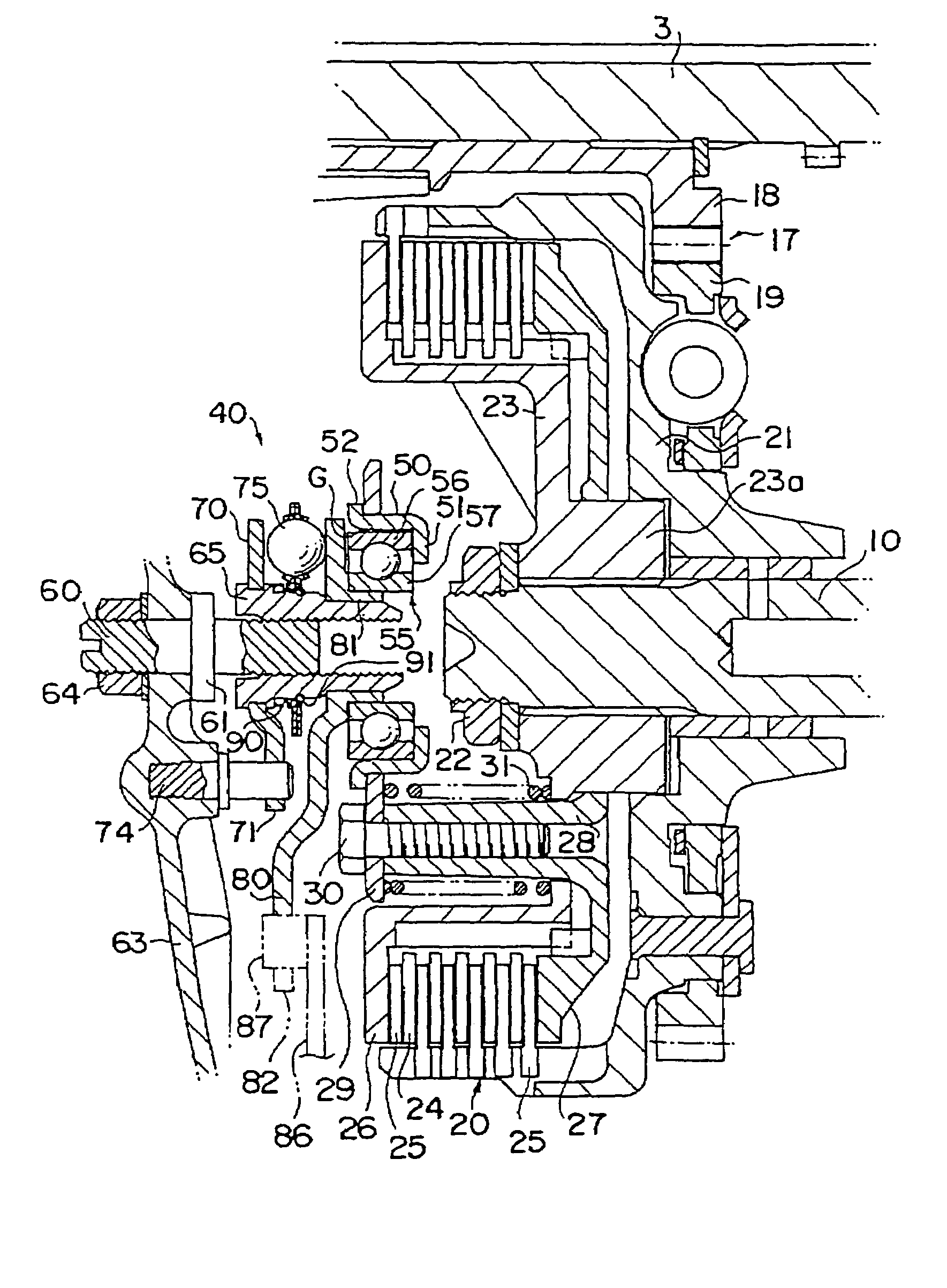
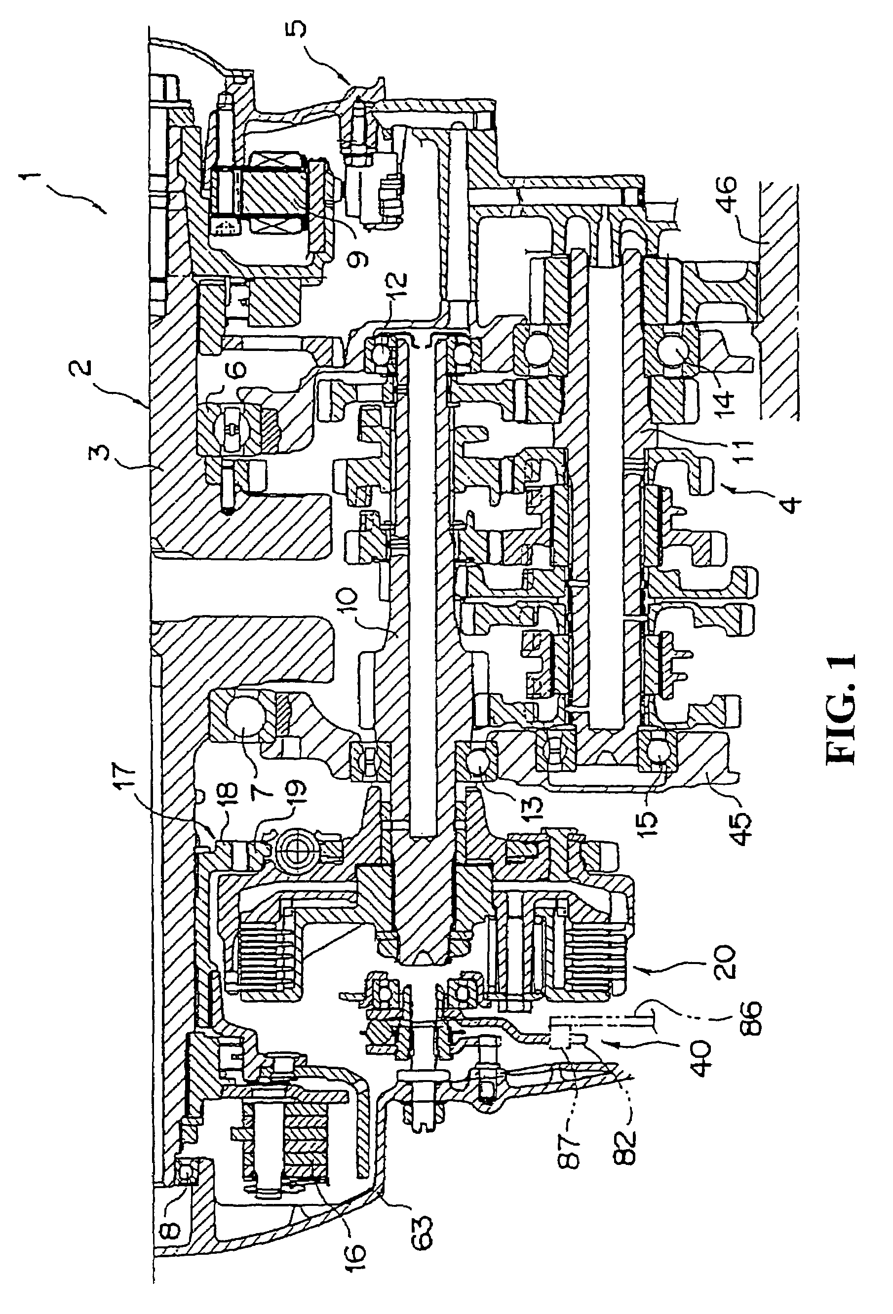
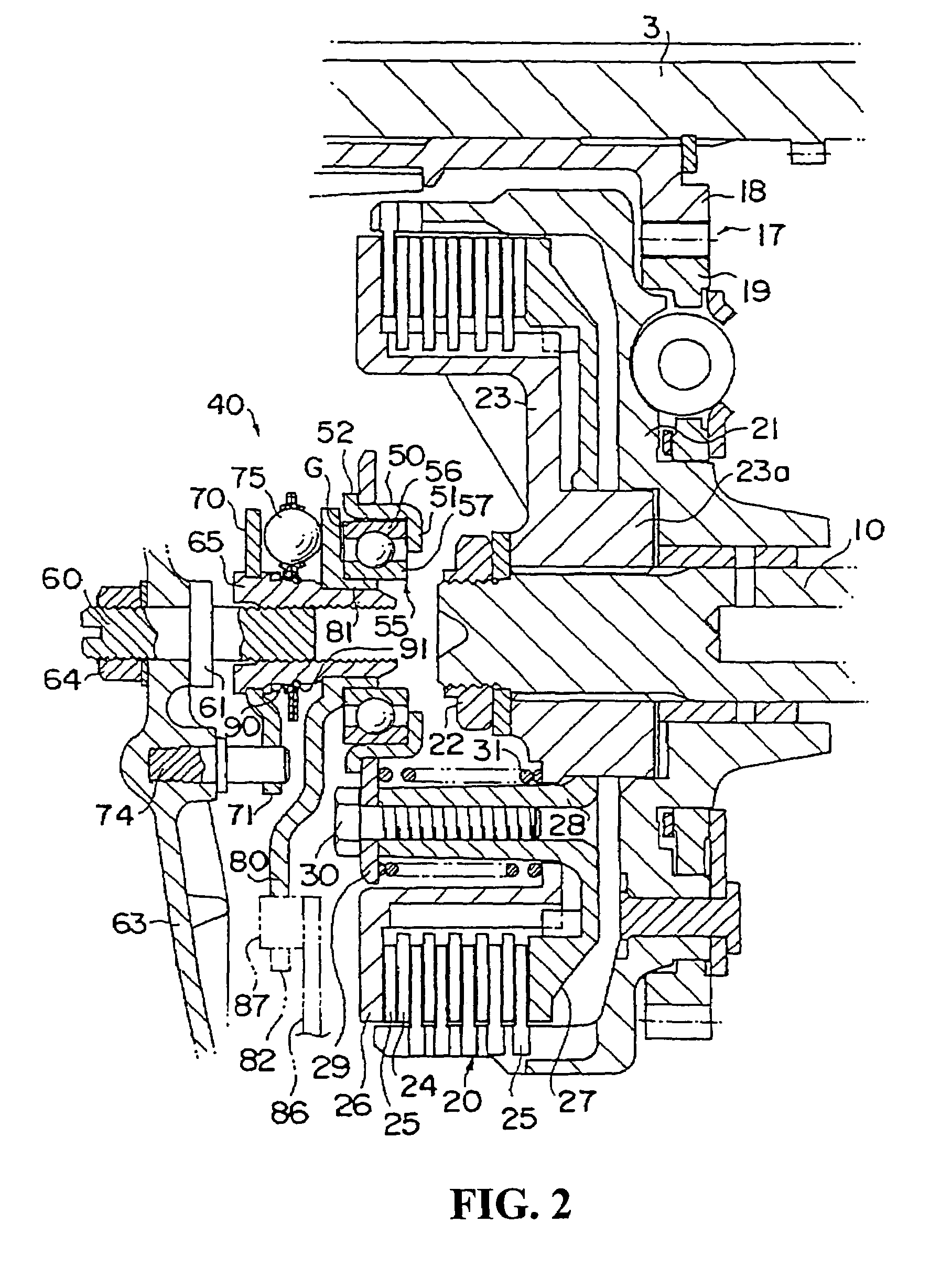
[0023]Referring now to the drawings, a preferred embodiment of the invention will be described. FIG. 1 shows a vehicle power unit 1 provided with a clutch release mechanism according to an embodiment of the present invention. The power unit 1 mainly includes an engine (internal combustion engine) 2, a transmission 4 for shifting gears and transmitting the speed of a rotational drive force of a crankshaft 3 of the engine 2 obtained thereby to a drive wheel, not shown, and a power unit case 5 for covering these components.

[0024]The crankshaft 3 of the engine 2 is rotatably supported by the power unit case 5 via ball bearings 6, 7, 8, and an ACG (alternating power generator) 9 is disposed at one end of the crankshaft 3. A main shaft 10 and a counter shaft 11 of the transmission 4 are disposed substantially in parallel with the crankshaft 3. The main shaft 10 is rotatably supported by a crankcase 45 which constitutes the power unit case 5 via ball bearings 12, 13. In addition, the count...


PUM


Abstract

To provide a clutch release mechanism which can restrain vibrations of a ball while allowing the ball to be loosely fitted when it is not in operation to ensure the engaged state of a clutch. A clutch release mechanism is configured in such a manner that a gap is defined between a clutch cam plate or a receiving plate and a ball unit so that the ball unit can slide between the clutch cam plate and the receiving plate. An urging spring is provided for urging the ball unit in the direction of being slid toward the clutch cam plate. A C-ring for restricting the ball unit from coming out from a boss member is attached to the peripheral portion of the boss member.

Description

CROSS-REFERENCE TO RELATED APPLICATIONS[0001]The present application claims priority under 35 USC 119 to Japanese Patent Application No. 2005-376520 filed on Dec. 27, 2005 the entire contents of which are hereby incorporated by reference.BACKGROUND OF THE INVENTION[0002]1. Field of the Invention[0003]The present invention relates to a clutch release mechanism for releasing engagement of a clutch device provided on a power unit in a motor cycle, a buggy or the like.[0004]2. Description of Background Art[0005]In the related art, there is a clutch release mechanism configured in such a manner that a ball is interposed between a fixed cam plate and a movable cam plate opposing to each other so that engagement of a clutch is released by pressing a release plate of a clutch device using a thrust force generated by the relative rotation of the both cam plates. See, for example, JP-A-2000-220660.[0006]When the clutch release mechanism in configured in this manner it is not in operation, it ...

Claims


Application Information

Patent Timeline
Patent Type & Authority Patents(United States)
IPC IPC(8): F16D13/00
CPCF16D13/56F16D2023/123
Inventor KOYAMA, SHINYAYOKOTANI, HITOSHIINUI, HIROATSU
Owner HONDA MOTOR CO LTD
Why Eureka
Try Eureka