Electrical connector and method of producing the same

a technology of electrical connectors and connectors, which is applied in the manufacture of contact members, coupling contact members, fixed connections, etc., can solve the problems of reducing contact reliability, and poor contact between the terminals and the terminals of mating connectors, so as to prevent poor contact between the terminals and the housing from becoming dusty, the effect of poor conta

Active Publication Date: 2009-09-22
HIROSE ELECTRIC GROUP +1
View PDF11 Cites 6 Cited by
  • Summary
  • Abstract
  • Description
  • Claims
  • Application Information

AI Technical Summary

Benefits of technology

[0010]In the electrical connector, the contact portion and the connection portion are provided on the first surface that is exposed and plated. Accordingly, when the electrical connector is used, the contact portions and the connection portions have good electrical contact characteristic and adhesive characteristic to solder. Further, a gap formed between the housing and the contact surfaces is reduced since the second surface adjacent to the housing is not plated. Accordingly, when soldered, rising of the flux to the gap is likely to be prevented.
[0014]Further, in the method of producing the electrical connector in the present invention, the electrical connector may be obtained by separating the carrier after the terminal portions and the housing are integrally formed and the carrier and the terminals are plated. Specifically, in the terminal structure that arranges a pair of the terminals in rows in parallel, all terminals may be plated at once after the terminal portions and the housing are integrally formed. Accordingly, the electrical connector may be produced easier than when the terminal portions and the housing are integrally formed after plating the terminal rows that are facing each other.
[0015]In the present invention, the terminals are plated after the terminal portions and the housing are integrally formed. Accordingly, the terminals are not likely to be deformed when plated. Further, a material of the housing or residue and dust yielded by plating may be cleaned and removed during a production process. Accordingly, a poor contact of the terminals due to an adherence of dust may be prevented.

Problems solved by technology

Further, when a size or a height of the connector is reduced, a contact between the terminals and the housing may become poor.
Accordingly, when the solder and the flux enter the gap between the housing and the terminals and reach the contact portions of the terminals, the contact between the terminals and the terminals of the mating connector may become poor, thereby reducing reliability of the contact.
Consequently, the contact of the terminals may become poor.

Method used


Image

  • Electrical connector and method of producing the same
  • Electrical connector and method of producing the same
  • Electrical connector and method of producing the same

Examples


Embodiment Construction

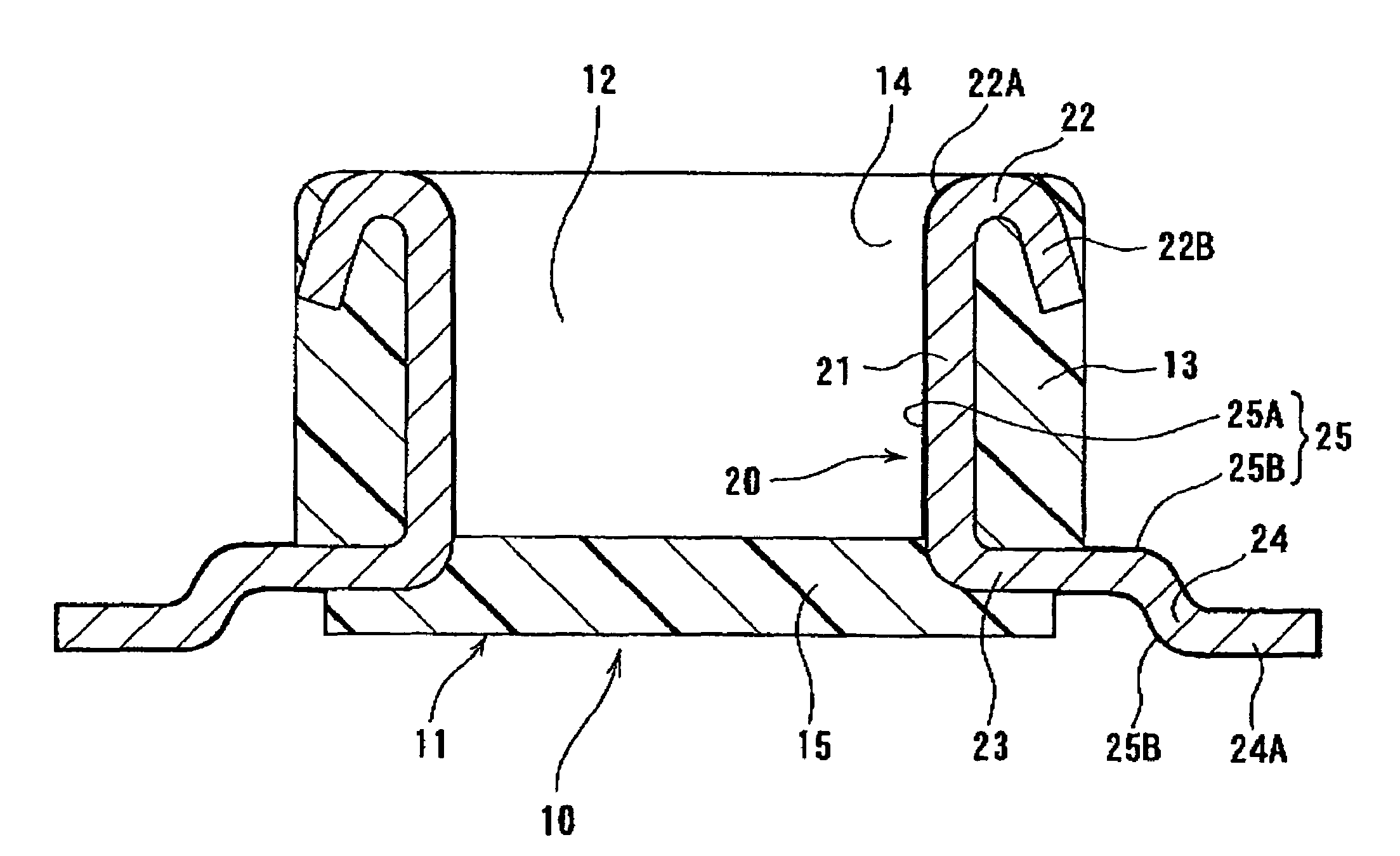
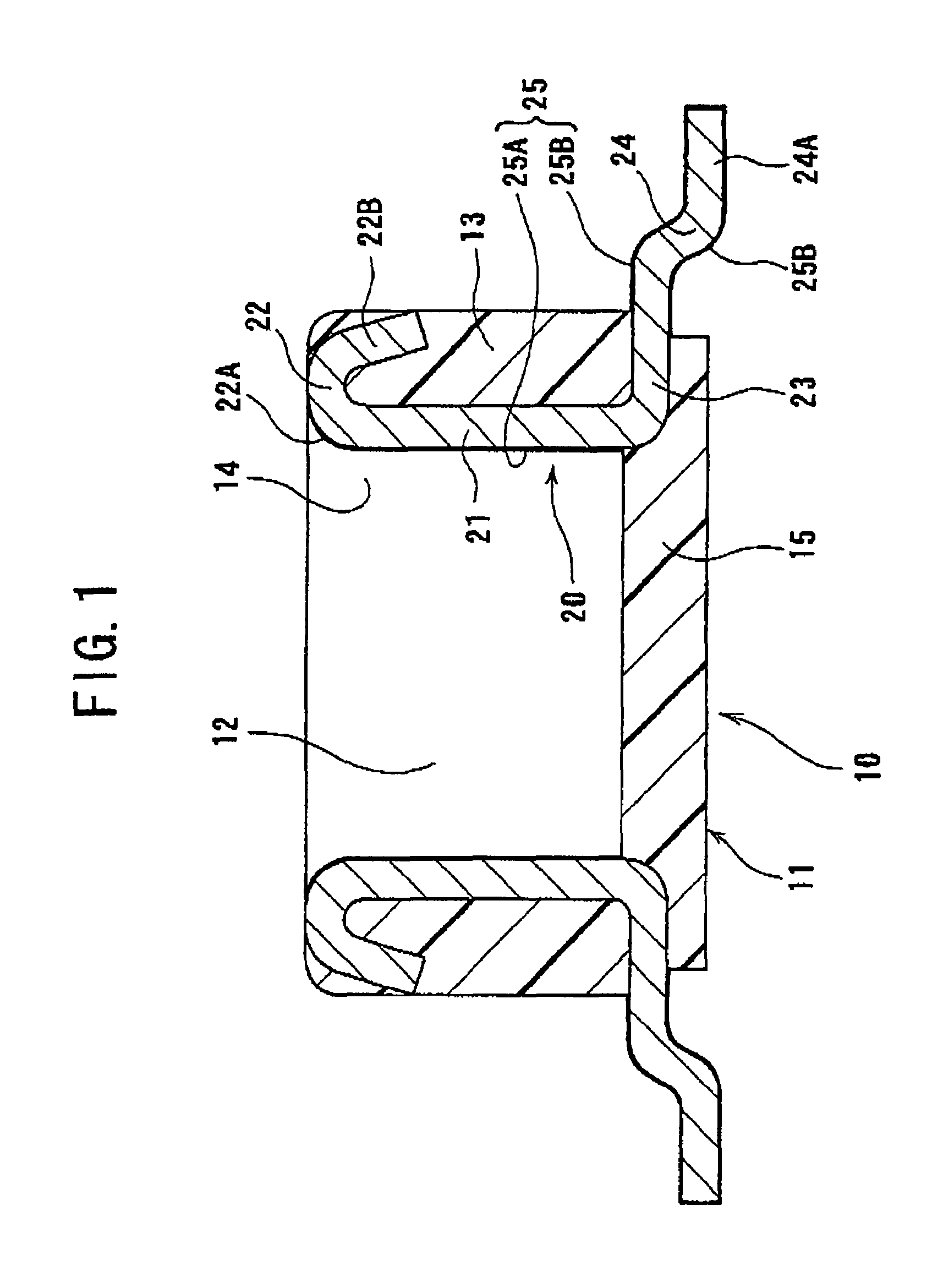
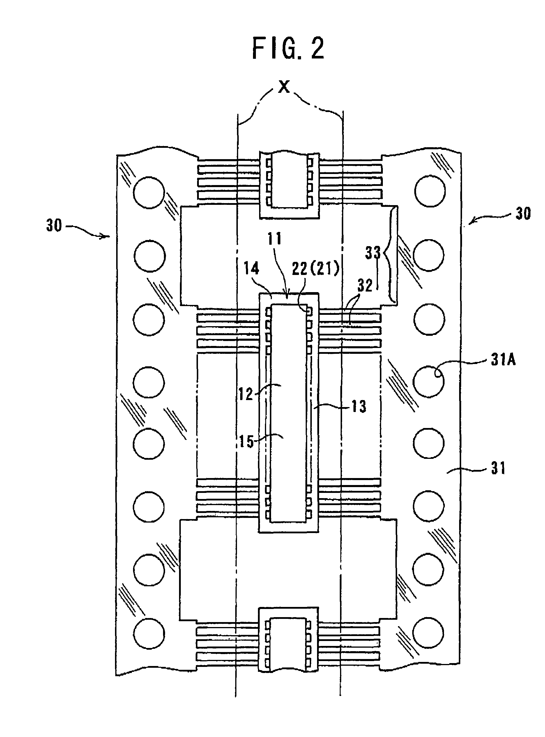
[0018]Hereunder, embodiments of the present invention will be explained with reference to the accompanying drawings. FIG. 1 is a vertical sectional view showing an electrical connector 10 of an embodiment in the present invention. FIG. 2 is a plan view showing a production process of the electrical connector 10 of FIG. 1.

[0019]As shown in FIG. 1, the electrical connector 10 is in a box shape having a bottom and includes a housing 11 formed by molding an insulating resin. The housing 11 is provided with a depressed portion 12 to receive a mating connector (not shown) therein. The electrical connector 10 extends in a direction perpendicular to a sheet surface of FIG. 1, and has a long rectangular shape in a plan view as shown in FIG. 2. Further, the housing 11 is provided with a pair of sidewalls 13, edge walls 14, and a bottom wall 15. The sidewalls 13 are in a long rectangular planar shape and extend in a longitudinal direction. The edge walls 14 connect end portions of the sidewall...


PUM


Abstract

An electrical connector comprises a housing and a terminal held by the housing. The terminal is provided with a first surface exposed form the housing and a second surface contacted with the housing. The first surface is plated, and the second surface is not plated.

Description

BACKGROUND OF THE INVENTION[0001]The present invention relates to an electrical connector and a method of producing the same. More specifically, the present invention relates to an electrical connector having terminals integrally formed with and held by a housing.[0002]In Patent Reference, an electrical connector having terminals integrally formed with and held by the housing is disclosed. When the electrical connector is produced, all surfaces of the terminals having a carrier that are integrally formed with the carrier are plated. Further, terminal portions and the housing are integrally formed, so that the terminals are held by the housing. Then, the electrical connector is obtained by separating the carrier.Patent Reference: Japanese Patent Publication No. 9-259989[0003]In the electrical connector disclosed in Patent Reference, all surfaces of the terminals having the carrier are plated before the terminal portions and the housing are integrally formed. At this time, at least al...

Claims


Application Information

Patent Timeline
Patent Type & Authority Patents(United States)
IPC IPC(8): H01R12/00
CPCH01R12/57H01R13/03H01R12/714H01R43/24H01R43/16
Inventor GOTO, MASAYUKIIKEDA, KAZUHIKOOSHITA, FUMIO
Owner HIROSE ELECTRIC GROUP
Why Eureka
Try Eureka