Power generator assembly comprising a non-rotating part and an electric device included on a rotating part

a technology of power generator and non-rotating part, which is applied in the direction of magnetic circuit rotating parts, vehicle energy devices, magnetic circuit shape/form/construction, etc., can solve the problems of limited space for a stator encompassing the rotor, and achieve the effect of reducing the net magnetic flux, reducing the leakage of magnetic flux, and increasing the net flux differen

Active Publication Date: 2020-07-28
AB SKF
View PDF10 Cites 5 Cited by
  • Summary
  • Abstract
  • Description
  • Claims
  • Application Information

AI Technical Summary

Benefits of technology

[0015]In a further development, leakage of magnetic flux is further reduced in that an additional permanent magnet is arranged between the adjacent pole shoes of at least the first and second generator units. Suitably, the direction of magnetization of the additional permanent magnet is such that the magnetic flux is oriented in the same direction as that of the adjacent pole shoes. The additional permanent magnet will be referred to as a guide magnet and has the effect of repelling stray magnetic flux, so as to guide the flux to the saddle adapter.
[0016]In a still further development, the power generating assembly comprises at least one shunt magnet which has the effect of increasing the net flux difference between maximum and minimum when a generator unit rotates between the first and second rotational positions. The at least one shunt magnet is arranged in proximity to at least one of the generator units and is configured to produce a magnetic field that is oppositely oriented from the magnetic field produced by the at least one generator unit. When the at least one generator unit is not underneath the saddle adaptor, i.e. in the “open” first rotational position, the shunt magnet reduces the net magnetic flux of the at least one generator unit. The magnetic flux may even become negative. When the generator unit is underneath the saddle adaptor, i.e. in the “closed”, second rotational position, the shunt magnet also reduces the net magnetic flux. However, the reduction in flux is relatively less when the unit is in the closed position, meaning that a greater difference between the maximum and minimum flux is achieved. This improves the power output of the generator unit.
[0021]According to a still further development, it is proposed that the saddle adaptor includes a main body part and at least one additional piece configured to increase the surface area of the saddle adaptor and / or decrease the air gap provided between the saddle adaptor and the pole shoes. In the case of a train axle box, the main body may be integrated in the saddle or saddle adapter of a saddle type train bogie suspension.
[0022]In one example, the at least one additional piece comprises a toothed radially inner surface, such that a varying radial gap is provided between the saddle adaptor and the pole shoes. This has the advantage of increasing flux change. In a further example, the radially inner surface of the saddle adapter is directly provided with such a toothed profile.

Problems solved by technology

In some applications, the room for a stator encompassing the rotor may be limited and be available only on one side.

Method used


Image

  • Power generator assembly comprising a non-rotating part and an electric device included on a rotating part
  • Power generator assembly comprising a non-rotating part and an electric device included on a rotating part
  • Power generator assembly comprising a non-rotating part and an electric device included on a rotating part

Examples


Embodiment Construction

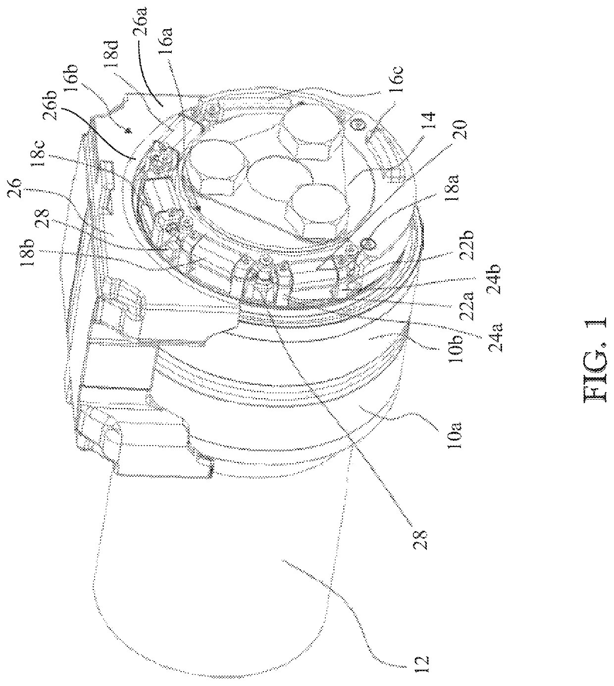
[0036]FIG. 1 is a schematic view of an end part of a train axle, wherein outer rings 10a, 10b of a double row tapered roller bearing configured to mount the axle 12 in the saddle type adapter 26 of a train bogie are visible.

[0037]An end cap 14 is fastened to an end face of the axle 12 by means of three bolts and preloads a split inner ring of the bearing in an axial direction. A rotating part 16a of a power generator assembly according to the invention is provided on an outer rim of the end cap 14. The outer rim of the end cap 14 is substantially divided in two halves. One section 16c houses the electronics and the other half includes multiple generator units 18a-18d. Four generator units 18a-18d are provided in the embodiment illustrated.

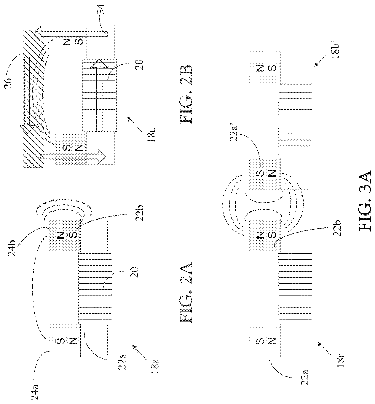
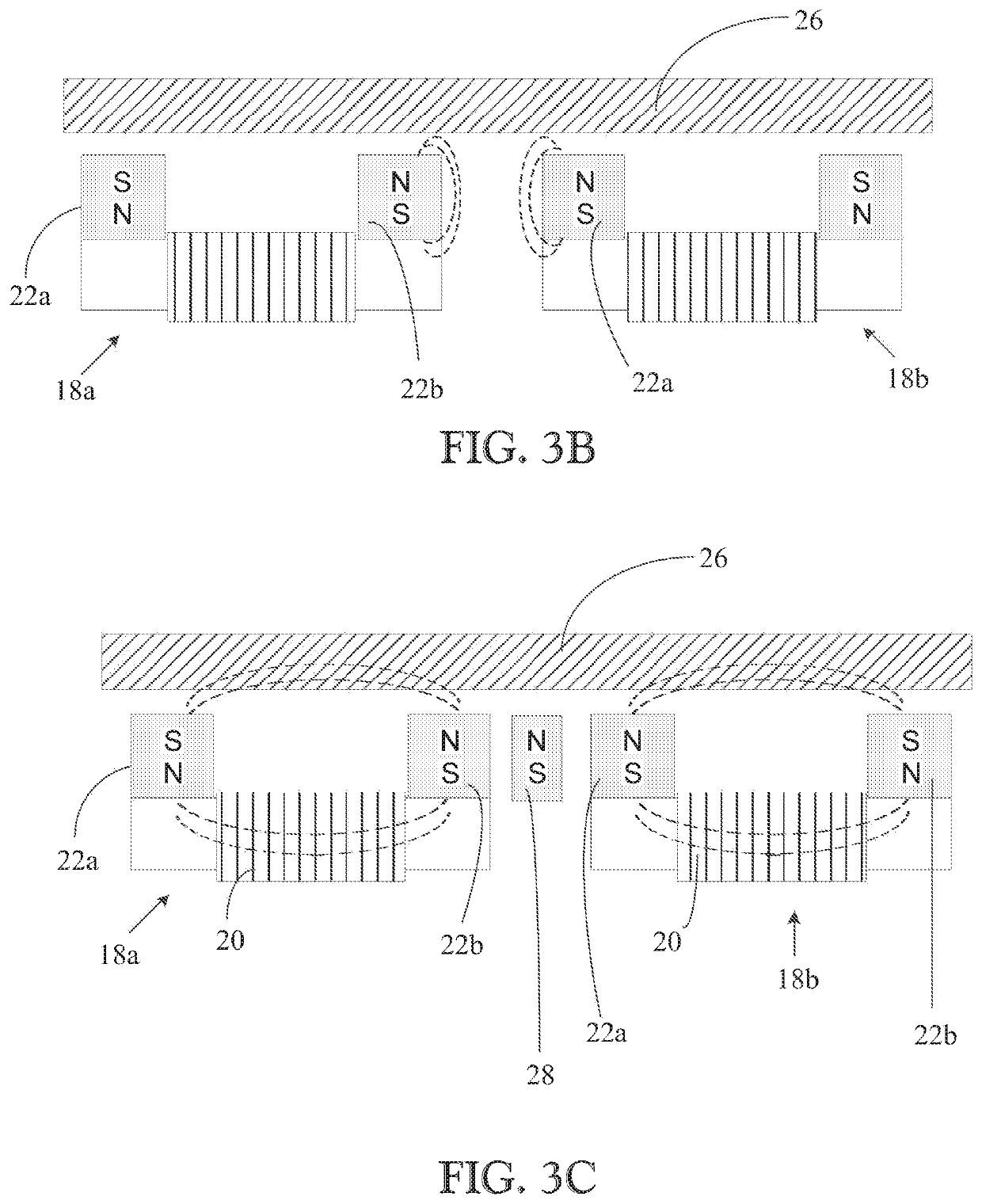
[0038]The power generator assembly includes the rotating part 16a and a non-rotating part 16b. The generator units 18a-18d are of modular type and essentially identical in configuration. Each of the generator units 18a-18d includes one coil 20 arra...


PUM


Abstract

A rotating part that includes at least one generator unit having at least one coil, at least one permanent magnet and two pole shoes having pole surfaces facing radially outward is provided, The non-rotating part has an arc-shaped saddle adaptor of ferromagnetic material arranged with a radial distance to the pole surfaces. The saddle adaptor is configured to close a magnetic circuit passing via the pole shoes through the coil in a rotational position where the saddle adaptor overlaps with the pole shoes of the generator unit.

Description

CROSS REFERENCE TO RELATED APPLICATIONS[0001]This is a United States National Stage Application claiming the benefit of International Application Number PCT / EP2016 / 052513 filed on Feb. 5, 2016, which claims the benefit of British Patent Application 1502097.7 filed on Feb. 9, 2015, both of which are incorporated herein by reference in their entireties.FIELD OF THE INVENTION[0002]The invention relates to a power generator assembly including a rotating part (16a) and a non-rotating part (16b).BACKGROUND OF THE INVENTION[0003]Power generator assemblies including a rotating part and a non-rotating part are widely known. A stator as a non-rotating part is then usually configured such that it encompasses the rotor as a rotating part completely.[0004]One type of generator assembly is a so-called variable reluctance generator wherein a magnetic circuit powered by a permanent magnet and passing through a coil is periodically opened and closed. The AC voltage induced in the coil as a result of...

Claims


Application Information

Patent Timeline
Patent Type & Authority Patents(United States)
IPC IPC(8): H02K7/18B61D43/00H02K21/44H02K21/10H02K11/042H02K7/04H02K1/22H02K1/14G01M17/10B61K9/00B61F15/20B61F5/50B61F5/14B61F15/00
CPCB61F5/14H02K21/10H02K11/042H02K7/04H02K1/223H02K1/14H02K7/1846B61F15/00B61K9/00B61D43/00H02K21/44G01M17/10B61F15/20B61F5/50Y02T30/36Y02T30/00H02K7/1861H02K11/0094H02K11/20
Inventor MCGOOGAN, GERARDANGELIS, GEORGOKUIJPERS, TOONVAN DER HAM, ANDREAS CLEMENS
Owner AB SKF
Why Eureka
Try Eureka